A band edge is a boundary of an amateur band or of a segment available to the control operator. In the United States, FCC §97.307(b) requires emissions resulting from modulation to stay within that available band or segment—not merely the frequency shown on a radio’s display. A display may give you a tuning reference while your signal occupies frequencies above or below it. Near an edge, the useful question is therefore not just “Is the dial inside?” but “Does the transmitted signal fit inside the boundary that applies to me?”
Which Edge Applies to Your Transmission?
First identify which boundary you are approaching. The outer edge of an amateur band is one possibility. Another is the edge of a segment available to the control operator, even though the amateur band continues beyond it. The FCC rule expressly refers to the “band or segment available to the control operator,” so being inside the broader band does not, by itself, answer whether your transmission fits your authorization.
For a US amateur, that means considering the privileges under which the control operator is transmitting and the authorization for the intended emission. A frequency can be inside an amateur band yet outside a segment available for that operator’s intended transmission. Conversely, the particular edge worth watching may be a segment boundary rather than the band’s outer limit. Identify the applicable boundary before deciding how close to it to transmit; otherwise, even a careful estimate of signal width is being compared with the wrong line.
Keep an FCC authorization boundary distinct from a voluntary band-plan recommendation. A band-plan recommendation can guide where operators choose to operate, but it does not enlarge the band or segment available to a control operator under FCC rules. Nor does the fact that a radio can receive on a frequency establish permission to transmit there. Reception tells you something about the receiver’s coverage, not the extent of your transmitting privileges.
Once you know the applicable boundary, §97.307(b) supplies the central test: emissions resulting from modulation must be confined to the band or segment available to the control operator. Modulation is what turns a tuning reference into a transmitted signal with frequency extent. The rule consequently concerns where the emission falls, rather than whether one displayed number happens to be on the permitted side of a line. A dial reading is useful information, but it cannot serve as a substitute for understanding what the radio will transmit.
What the Radio’s Frequency Display Represents
Think of a sideband signal as occupying space on one side of a carrier reference. With upper sideband, or USB, the illustrated signal components are above that reference; with lower sideband, or LSB, they are below it. Other modulated signals also occupy a range of frequencies. A single displayed frequency does not describe the full extent of any such transmission.
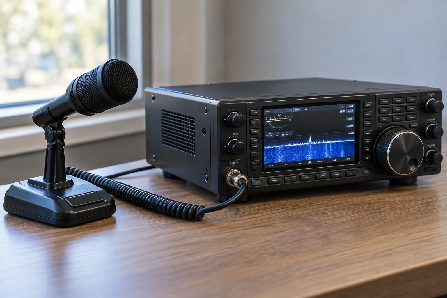
There is a second question: which frequency is the display showing? A 2002 ARRL QST technical article notes that a transceiver may display its receive frequency or its transmit frequency, depending on the manufacturer and, potentially, the radio’s configuration. Thus, even before allowing for signal width, do not assume that the number you see is the reference the transmitter will use. Split operation or another transmit offset can make the distinction especially important. Read the actual radio’s display and transmit configuration, rather than relying on what a similar-looking display usually means.
It also helps to separate three properties that are easily mistaken for one another. Resolution is how finely the display lets you read or set a frequency—for example, whether it shows additional digits. Accuracy concerns how close the actual transmitted frequency is to the intended or indicated value. Stability concerns how consistently it stays there. More displayed digits improve neither accuracy nor stability by themselves. Near a boundary, the question is where the transmitted signal actually falls, including any uncertainty in its reference frequency, not how precise the screen looks.
These distinctions form a useful mental picture: the display may identify a receive or transmit reference; the chosen modulation extends the transmission around or to one side of its transmit reference; and the applicable band or segment edge limits the resulting emission. Each part matters. A perfectly identified reference does not make the signal zero-width, while a good estimate of width is of little use if you have mistaken the receive frequency for the transmit frequency.
How a Sideband Signal Can Cross an Edge
The ARRL article’s USB table provides a compact illustration. It lists a 14,200.00 kHz carrier reference and a range of 14,200.30–14,203.00 kHz for the USB example. The arithmetic becomes clearer if we assume audio offsets from 300 to 3,000 Hz. Since 300 Hz is 0.30 kHz and 3,000 Hz is 3.00 kHz:
- Lower illustrated component: 14,200.00 + 0.30 = 14,200.30 kHz
- Upper illustrated component: 14,200.00 + 3.00 = 14,203.00 kHz
The reference is 14,200.00 kHz, but the illustrated upper component is 3.00 kHz higher. Looking only at the reference would conceal that difference. This is a simplified way to understand the table, not a measured emission mask, a statement that real filters stop abruptly at either endpoint, or a current legal channel assignment. The 2002 article is useful here for its technical illustration, not as authority for any historical operating boundaries it may discuss.
Now consider an original, purely hypothetical upper boundary called F. Suppose a USB transmitter’s reference is set at F − 1 kHz, and assume an upper audio offset of 3 kHz. The illustrated upper component is:
(F − 1 kHz) + 3 kHz = F + 2 kHz
Although the reference is 1 kHz inside the hypothetical limit, that illustrated component lands 2 kHz beyond it. If F represents the applicable upper edge, the setup fails the whole-signal test illustrated by FCC §97.307(b); the inside dial reference does not rescue a component outside the available band or segment. The calculation is a geometry example, not permission to transmit at any particular frequency and not a prediction of a real radio’s exact emission extent.
Reverse the situation for LSB near a lower edge. Because the illustrated LSB components fall below their reference, setting the reference just above a lower boundary can still leave part of the signal below that boundary. The sideband determines which direction from the reference needs particular attention: USB near an upper edge and LSB near a lower edge make the risk especially easy to picture. The broader principle does not depend on sideband, though. For any mode, compare the transmitted emission’s extent with the boundary that applies to the control operator.
Choosing Room Inside the Permitted Segment
A responsible near-edge decision follows from the mental picture rather than from a universal dial setting. Establish the band or segment boundary available for the intended transmission. Identify the actual transmit mode and its bandwidth. Determine what the radio displays—receive frequency, transmit frequency, or a configurable reference—and whether split operation or another offset changes the transmit reference. Then allow for the radio’s frequency accuracy and stability when judging how much room the actual signal has.
The signal’s width also depends on more than the neat offsets in an illustration. For phone operation, the 2002 ARRL article identifies the shapes of the audio and sideband filters, along with microphone gain, compression and ALC settings, as factors affecting signal width. That is why the 3 kHz upper offset in the examples is useful arithmetic but not a guaranteed boundary for every transmission. It shows how to think about direction and extent; it does not certify a setting on an unexamined radio.
Two related FCC requirements deserve separate attention. One says an amateur transmission must not occupy more bandwidth than necessary for its information rate and emission type, in accordance with good amateur practice. Another says emissions outside the necessary bandwidth must not cause splatter or keyclick interference to operations on adjacent frequencies. Keeping the intended signal inside an authorized boundary is not a reason to ignore unnecessary width or unwanted emissions. Equally, selecting a suitable bandwidth does not make it acceptable for modulation emissions to extend beyond the band or segment available to the control operator.
That distinction changes the practical decision. If the applicable boundary and the actual transmit configuration are clear, and you can account for the signal’s extent and the radio’s frequency uncertainty, choose a reference that leaves the transmission inside the permitted segment—not merely a reference that reads inside it. If you cannot establish the actual extent with confidence, use suitable bandwidth, control unwanted emissions, and move farther inside the segment rather than treating a guessed offset as proof of compliance. If you cannot tell what frequency the radio will transmit on, resolve that configuration question before transmitting near the edge.
There is no single setback that guarantees the result for all modes, settings and radios. The 14,200.00 kHz example explains why a USB reference can have components above it; the hypothetical F example explains how an apparently safe reference can still put an illustrated component across an upper limit. Neither supplies a universal number to subtract from every edge. The operational test remains the same: the relevant band or segment boundary must contain the modulated transmission, not merely the frequency displayed on the radio.