A decibel, written dB, expresses a ratio. In radio power comparisons, about +3 dB means twice the power, −3 dB means half, and +10 dB means ten times as much. The reference matters: “3 dB more” describes a change, while “3 dBm” describes a power level relative to one milliwatt.
Once you separate ratios from referenced levels, cable-loss specifications, antenna figures and received-signal readings become easier to interpret. Start with ordinary watts, then use dB to keep track of what changes between two points in a station. You do not need to begin by memorizing logarithm tables.
Read the Number as a Comparison
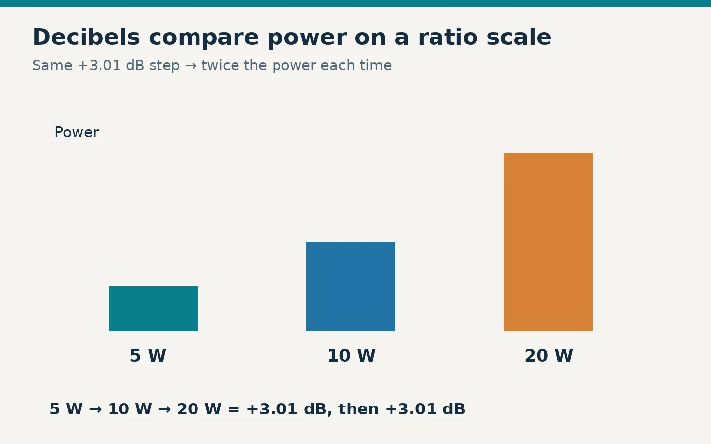
Imagine an illustrative transmitter whose output can be set to 5 W, 10 W or 20 W. Moving from 5 W to 10 W doubles the power. Moving from 10 W to 20 W doubles it again. Each move is about +3 dB, even though the first adds 5 W and the second adds 10 W.
A dB step describes the multiplication, not a fixed number of extra watts. That is why the same language works for tiny receiver signals and much larger transmitter outputs. A 3 dB increase at either scale is approximately a doubling of power; it does not make those two starting powers equal.
The sign tells you which way the comparison goes. If the reference is 20 W and the output is 10 W, the change is approximately −3 dB. A specification calling this “3 dB of loss” is giving the positive magnitude of the loss. In a gain calculation, enter it as −3 dB rather than adding it as a gain. Zero dB means equal powers, not an absence of RF energy.
Use the Power Shortcuts, Then the Formula
The following values are rounded teaching shortcuts. Use the exact formula when the last decimal place matters.
| Power change | Approximate ratio: final ÷ initial | Example |
|---|---|---|
| −10 dB | 0.1 | 50 W becomes 5 W |
| −6 dB | 0.25 | 20 W becomes about 5 W |
| −3 dB | 0.5 | 10 W becomes about 5 W |
| 0 dB | 1 | 10 W remains 10 W |
| +3 dB | 2 | 5 W becomes about 10 W |
| +6 dB | 4 | 5 W becomes about 20 W |
| +10 dB | 10 | 5 W becomes 50 W |
| +20 dB | 100 | 0.1 W becomes 10 W |
For any positive power values, the formula is:
Change in dB = 10 × log10(final power ÷ initial power).
Use the same units above and below the division. If you compare 25 W with 10 W, enter 25 ÷ 10 = 2.5, take the base-ten logarithm, then multiply by ten. The result is about +3.98 dB. If you reverse the comparison, 10 ÷ 25, the result is −3.98 dB. On a scientific calculator, log normally means base ten; ln is a different function.
To go back from dB to a power multiplier, calculate 10 raised to (dB ÷ 10). For example, −2 dB gives 10^(−2/10) = 0.631. A 10 W signal after 2 dB of loss is therefore about 6.31 W. The minus sign belongs inside the exponent.
These examples also show why the common shortcuts are approximate. An exact doubling is about 3.0103 dB, while exactly 3 dB multiplies power by about 1.995. For everyday estimates the distinction is small, but do not manufacture precision by treating a rounded shortcut as an exact equality.
Distinguish dB, dBm and dBW
A suffix supplies a reference. dBm uses one milliwatt; dBW uses one watt. Both describe actual power levels. Plain dB, on its own, does not tell you how many watts are present.
For a power expressed in milliwatts, calculate dBm = 10 × log10(power in mW). For watts, calculate dBW = 10 × log10(power in W). Because one watt is one thousand milliwatts, the same power has a dBm value 30 larger than its dBW value.
| Actual power | dBm | dBW |
|---|---|---|
| 1 mW | 0 | −30 |
| 10 mW | +10 | −20 |
| 1 W | +30 | 0 |
| 5 W | about +36.99 | about +6.99 |
| 10 W | +40 | +10 |
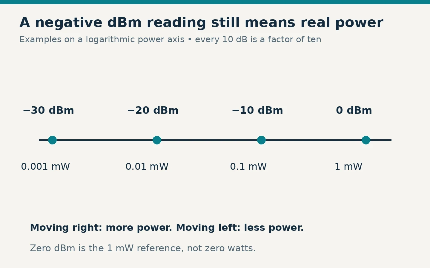
A negative dBm reading does not mean negative physical power. It means the power is below the one-milliwatt reference. For example, −30 dBm is 0.001 mW, or one microwatt. At the receiver, −90 dBm is a stronger power level than −100 dBm: it is ten dB higher and therefore ten times the power.
Subtracting two power levels in dBm gives a difference in dB. A change from −100 dBm to −90 dBm is −90 − (−100) = +10 dB. Do not describe that change as “+10 dBm stronger.” Likewise, add a gain or subtract a loss from a dBm level, but do not add two unrelated dBm readings as though they were ordinary watts.
Ask What the Antenna Figure Is Referenced to
Antenna specifications commonly use dBi, referenced to an ideal isotropic antenna, or dBd, referenced to a half-wave dipole in free space. These are antenna gain comparisons. They are not transmitter-output readings like dBm.
The reference is part of the specification. If one advertisement says 5 dBi and another says 5 dBd, their matching numeral does not establish equal gain. Ask for figures on the same reference, at the same frequency and under comparable conditions. A bare “5 dB gain” without a reference is incomplete for a careful comparison.
An antenna's gain describes directional radiation relative to its reference. It does not mean an unpowered antenna creates additional transmitter energy. A useful way to reason about the pattern is to ask where energy is concentrated and where it is reduced. More gain toward a desired direction can help that path, but a narrower useful pattern can also make pointing more important.
For a beginner choosing an antenna, gain is therefore one input. The intended direction, mounting height, operating band, feed line and installation constraints can change the result. Do not turn a catalog gain number into a guaranteed distance or assume it gives the same improvement at every elevation.
Add Gains and Losses Through One Station
Consider an illustrative station with a 10 W transmitter, 2 dB of total feed-line loss and an antenna rated at 5 dBi in the direction of interest. Begin at the transmitter connector:
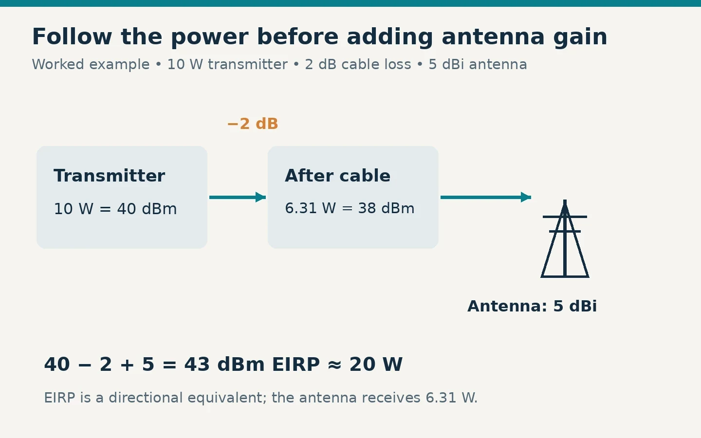
- Convert 10 W into a referenced power level: 40 dBm.
- Subtract the cable loss:
40 − 2 = 38 dBm, about 6.31 W at the antenna input. - Add the directional antenna gain:
38 + 5 = 43 dBmof equivalent isotropically radiated power, or EIRP, about 20 W.
EIRP expresses how much power an ideal isotropic radiator would need to produce the same strength in that direction. The antenna still receives about 6.31 W through the cable. Calling the 20 W directional equivalent “actual power coming out of the antenna connector” would confuse two different quantities.
If the cable loss were reduced from 2 dB to 1 dB while everything else stayed the same, the gain in that path would be 1 dB. The multiplier is 10^(1/10), about 1.26. This gives you a consistent way to compare an incremental feed-line improvement with an incremental transmitter-power increase.
Use the cable maker's loss at your frequency and length, plus relevant connectors and other losses. A loss figure for 100 feet of cable is not automatically the loss of your 25-foot lead, and a figure measured at one band should not silently become the value for another. The chain is only as good as its inputs.
Use 20 Log for Voltage Only Under the Right Condition
Power in a resistor depends on the square of voltage: P = V² ÷ R. When the compared impedances are equal, a voltage ratio can therefore be expressed as 20 × log10(final voltage ÷ initial voltage). Doubling voltage across the same resistance produces four times the power, about +6.02 dB, rather than +3.01 dB.
The equal-impedance condition is essential. If the impedances differ, calculate the powers using the actual circuit conditions and then apply the power-ratio formula. Do not use a voltage ratio alone to claim a power gain across unlike loads. This is also why a voltage-sensitivity figure needs its impedance and reference before it can be compared with a receiver power level.
For ordinary transmitter wattage and cable-loss examples, stay with the ten-log power formula. It avoids introducing a voltage assumption you do not need.
Interpret Stronger Signals Without Promising a Better Contact
Signal-to-noise ratio, or SNR, compares wanted signal power with noise power under specified measurement conditions. It is a ratio in dB, not an absolute received power in dBm. A signal can become stronger while its SNR remains unchanged if the noise rises by the same amount. Keep measurement bandwidth and settings consistent when comparing receiver readings.
A radio's S-meter is useful operating feedback, but it is not automatically a calibrated power instrument. The ARRL tutorial cautions that many receiver S-meters are not accurately calibrated. Do not promise that a particular power change will move every radio by an exact number of S-units.
When you next read a dB specification, ask three things: “Compared with what?”, “At which point and under which conditions?”, and “Am I looking at a ratio or a referenced level?” Those checks let you use the arithmetic without confusing a stronger number with a guaranteed communications result.