To set up a ham radio station, start with one operating purpose and one location. Choose a band and mode your U.S. license permits, then match a transceiver, its power source, a feed line and an antenna system. Compare the exact equipment manuals before applying power. Resolve installation hazards and RF-exposure questions before transmitting, verify your authority to operate, and make a brief first test at the settings you checked. A modest station you can understand and assess is a better starting point than a collection of equipment you have not yet matched.
Choose the Station You Will Actually Use
Decide what you want the first station to do. For example, you might want to try local contacts from a desk, or you might be interested in longer-distance contacts from the same location. Those are illustrative goals, not equipment prescriptions: each points you toward different questions about the radio and antenna. ARRL notes that antenna choices depend in part on whether you start on HF or VHF.
Choose either a simple fixed position or a portable setup at one known location. A fixed position lets you assess the same space and cable route each time. For a portable station, identify where it will be used and assess that location before operating; do not assume that checks made elsewhere carry over. Leave elaborate portable and mobile installations for later.
Before buying or connecting equipment, identify the band and mode you intend to use and check that the operation fits your U.S. license class. Use the current FCC amateur rules and your license information for that decision, rather than a band chart remembered from another operator or a generic power figure in shopping advice. Note the date on which you checked: privileges and the configuration you plan to use are more useful as a recorded decision than as an assumption.
Sketch the proposed operating position and an antenna location you can assess without hazardous installation work. Can the equipment sit securely? Is there a plausible cable route? Will you be able to identify where people may be in relation to the antenna during transmission? These planning questions can eliminate an unsuitable location before you spend money.
You can plan the station, assemble a list of compatible parts and listen to signals without treating that activity as permission to transmit. Transmitting is a separate decision, governed by your operating authority and the safety checks below. Keep the first goal narrow enough that you can explain why every component and setting belongs in this particular setup.
Map the Radio, Power and Antenna System
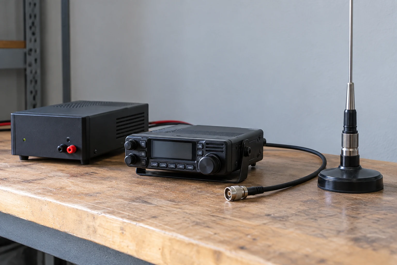
ARRL groups the transceiver, power supply and antenna system as basic station components. For a beginner using commercially assembled equipment, it helps to expand that grouping into a conceptual path:
Compatible DC source → transceiver → feed line → antenna
This is a planning map, not a manufacturer-specific wiring instruction or a required order for making connections. Some equipment arrangements do not call for a separate external supply. Follow the manuals for the models you actually own when it is time to connect and power them.
The transceiver is the radio used to receive signals and, when operation is authorized and the station is ready, transmit them. The DC source supplies the electrical input specified for that radio; in this setup it might be a compatible supply or battery. “Compatible” must come from matching the products’ documentation, not from assuming that two items intended for amateur radio will work together.
The feed line is the radio-frequency, or RF, path between radio and antenna. ARRL describes it as the conduit between those two components and explains that loss at a given frequency varies considerably among feed-line types. ARRL also states generally that amateur transceivers are designed to work with a 50-ohm impedance interface. That general statement is a reason to check the intended antenna system against the particular radio’s requirements; it does not establish the specification of a product you have not identified.
The antenna system is what makes the radio’s RF signal usable beyond its antenna port and allows incoming signals to reach the receiver. Give it as much planning attention as the transceiver. ARRL cautions that a poor antenna system can waste much of the investment in a radio. That does not predict how far your first station will reach; it means antenna suitability, location and the feed-line route should be part of the initial choice rather than afterthoughts.
Think of the map as four questions you must be able to answer: What powers this radio? What antenna-port requirements does it specify? What path will the feed line take? Where can the antenna be used safely and assessed for RF exposure? The answer might reveal that a proposed location or component is unsuitable. It is fine to change the plan at that point.
This modest map deliberately stops short of specialist installation work. It does not tell you to build a power connection, modify electrical wiring, install an antenna on a roof or tower, or alter station grounding. Nor does it replace the model manuals’ connection instructions. Its job is to make the interfaces visible so you know what to verify before anything is powered.
Check Compatibility and Placement Before Applying Power
Collect the manuals or manufacturer documentation for the exact model of transceiver, supply or battery, and intended antenna-system components. Record model identifiers, including variants that may have different connectors or requirements. Compare the radio’s requirements with a prospective supply before buying. ARRL advises reading equipment specifications before purchase; its guidance also identifies the supply’s continuous current rating as the figure to check, rather than relying on a prominent headline figure.
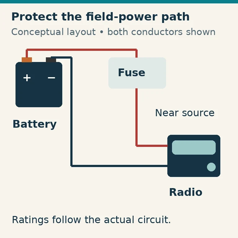
Start with the radio’s documented input requirements. Compare its specified input voltage and current needs with the source’s documented output and continuous capability. Then compare the required polarity and connector information on both sides. These are reading and identification checks, not an invitation to probe, modify or assemble electrical connections. Generic station ratings cannot settle a mismatch between your two actual products. The model manuals control the voltage, polarity, connectors and power procedures.
Next, compare the radio’s documented antenna-port requirements with the proposed feed line and antenna connections. Check the connector descriptions, the stated suitability of the components for your intended band and the feed-line route you would need. Because feed-line loss varies by frequency and type, two apparently convenient routes or line choices need not be equivalent. You do not need to predict a precise loss figure to recognize that the line type, operating frequency and route are worth checking against product information.
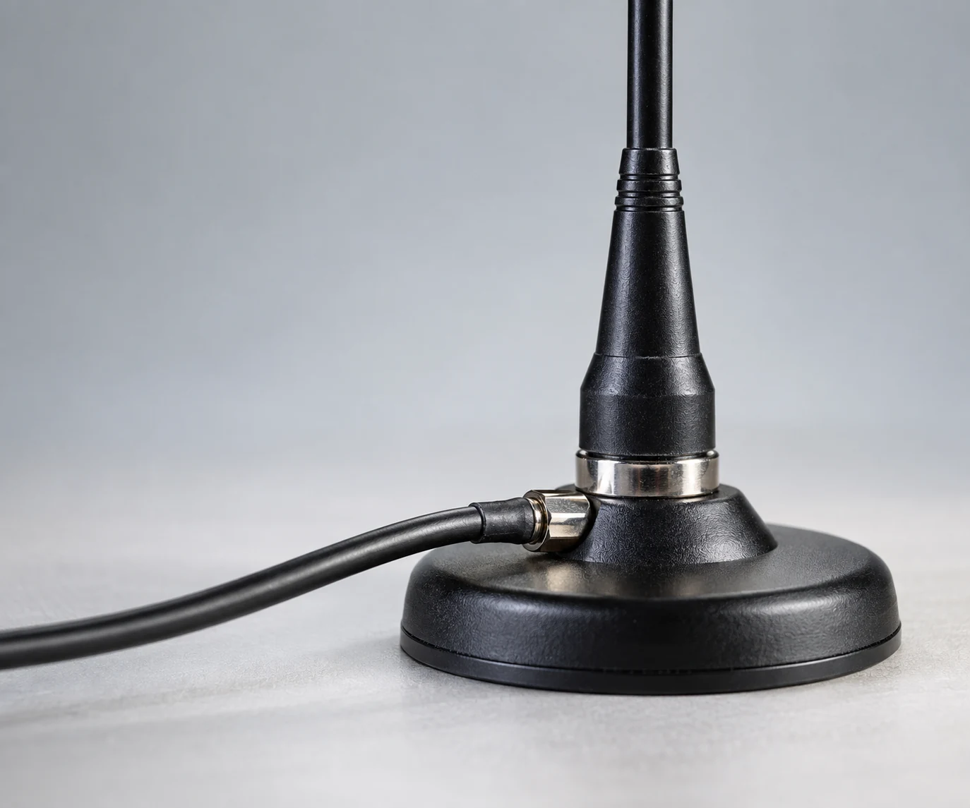
Walk through the location on paper before connecting anything. Put the proposed radio and source on a stable surface with controls and instructions accessible. Trace where each cable would go and look for an obvious trip risk, pinch point or place where the cable could be damaged. These are practical planning checks, not rules attributed to the FCC or promises that a location is electrically safe. If the only workable route involves hazardous installation work, change the plan or seek qualified help.
A short conceptual check record can keep the comparison honest. For each interface, write down the two items being compared, the relevant manual pages or labels, and whether their requirements agree. For example, a record might say “radio input versus source output: unresolved—connector description differs.” It should not supply a guessed adapter, a generic voltage or a claimed test result. The record is your aid to a decision, not a manufacturer checklist.
Stop with the equipment unpowered if a manual or label is missing, a connector or polarity cannot be identified, a required rating is unclear, or two specifications cannot be reconciled. Ask the manufacturer, an experienced club operator or an appropriately qualified technician to help resolve the particular discrepancy. Do not rewire a connector or improvise an adapter to make the parts fit. A successful visual match alone is not evidence of electrical compatibility.
Clear Site Hazards and RF Exposure Before Transmitting
Do not undertake antenna work near power lines. ARRL specifically warns operators to protect themselves when putting up antennas near them. If the proposed location or route presents that hazard, stop and seek qualified help or choose another setup; this guide provides no antenna-placement procedure for that situation.
Consider other site hazards before using the station. Lightning exposure and station grounding are substantial, site-specific safety questions. ARRL identifies station grounding as a major amateur-radio safety topic. These considerations do not supply a universal grounding scheme for your building or portable location. If protection or grounding work is needed, obtain appropriately qualified help rather than altering grounding or mains wiring from a generic diagram. Roof and tower work are outside this beginner setup as well.
There is also a distinct pre-transmission requirement: under 47 CFR § 97.13, the licensee must ensure compliance with applicable FCC RF-exposure requirements. Receiving a signal, finding the equipment comfortable to use, or selecting a low transmit setting does not by itself resolve that obligation. Assess the actual proposed configuration before transmitting.
Gather the information an appropriate assessment method needs: power at the antenna, operating frequency, antenna gain, mode duty cycle, transmit duty cycle, and the antenna’s position and relevant directionality relative to people. ARRL’s RF Exposure Calculator asks for power, gain, frequency and duty-cycle parameters. Its guidance also says ground reflections may matter and that multiple calculations may be needed to account for antenna lobes and directionality. A single entered set of values is therefore not automatically a complete picture of every location where exposure could occur.
ARRL says its calculator should not be used for an antenna less than 20 cm (8 inches) from a person. If that describes the proposed use, choose an appropriate assessment method or obtain qualified guidance instead. The same stop decision applies if necessary inputs are unknown or you cannot evaluate relevant positions and directions. Where the calculator is applicable, use it as an assessment tool with the actual configuration’s inputs—not as a promise that merely filling in a form establishes compliance.
Resolve these questions while the station remains receive-only. An unresolved electrical requirement, hazardous installation route, lightning or grounding question that needs design work, or RF-exposure assessment is a no-go for transmission. Trying a short or low-power transmission is not a substitute for resolving it. Change the location or configuration, obtain the missing information, or seek qualified help before reconsidering the test.
Power up, Listen and Document a First Test
Once the component comparisons and site assessment are resolved, use the exact model manuals to make connections and power up. Follow their procedures rather than a universal sequence of switches or plugs. Check that the radio shows the intended band and mode, and identify the available settings you will use. If the equipment behaves unexpectedly during power-up, stop and return to its documentation instead of proceeding toward a transmission.
Listen first. Receiving is a practical way to check that the radio is producing usable audio and to notice activity on the frequency you intended to use. It can help you avoid interrupting a communication already in progress. It does not prove that the transmitting configuration, electrical installation or RF-exposure assessment is safe.
Immediately before transmitting, if you are a new U.S. licensee operating your own station alone, verify your qualifying amateur license grant in the ULS consolidated license database and recheck that the chosen band, mode and operation are within your authority. Section 97.5 identifies physical control by a person named in an amateur station license grant in ULS as one licensing route. This check is scoped to the new operator using their own station alone; it is not a claim that supervised guest or reciprocal operation is prohibited. Record when you checked your grant and the applicable current rules.
Transmit only after that authority check, the equipment settings and the RF-exposure assessment are resolved for the configuration in front of you. Make a brief, appropriately authorized on-air test at the settings you checked. Observe what the equipment does and what you hear; do not treat one successful exchange as a test of every possible band, power setting, antenna position or location. If transmission does not behave as expected, stop transmitting. Return to the manuals and seek experienced or qualified help as needed rather than changing wiring or installation hardware by guesswork.
Finish the conceptual check record with the location and equipment models, the manual comparisons, the operating settings, the basis of the exposure assessment, and what you heard or observed. It helps you identify what changed if a later test differs; it is neither a manufacturer checklist nor a substitute for compliance. The station is ready for further use only while its components, location, operating authority and safety assessment remain consistent with the configuration you checked and tested.