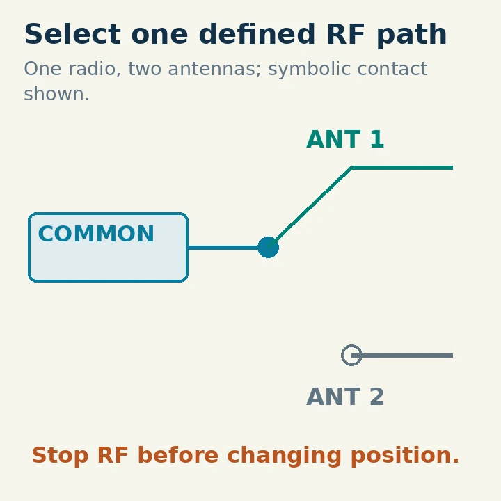
An antenna switch selects an RF path between a common connector and one of several other connectors. In a typical small station, it lets one transceiver use a dipole, a vertical or a dummy load without repeatedly moving coax plugs. Choose it for the actual frequencies, power, duty cycle, connector arrangement and switching job. Then label the paths and change position with transmission stopped.
The important question is what the switch connects in every position. A convenient knob does not by itself provide transmitter interlocking, lightning protection or a suitable termination for an unused radio.
First Draw the Station You Want to Switch
For one radio and two antennas, the radio normally connects to COMMON and the antennas to the numbered ports. A manual coax switch is often enough when everything is within reach. A remote switch puts the RF contacts near an outside feed-line junction and uses a separate control arrangement. That can reduce the number of long coax runs, but adds control wiring, power, weather exposure and another item to troubleshoot.
A different job is selecting one antenna for two radios. A switch may be electrically reciprocal, yet that does not establish that every unused port is safely isolated or that either radio can transmit in every state. Look for explicit manufacturer approval for the arrangement and the necessary transmit protection. Two transmitters connected accidentally can damage each other's receiver inputs.
Write the ports on paper before buying anything: RADIO, DIPOLE, VERTICAL and DUMMY LOAD, for example. Add the tuner and any amplifier. Trace the complete path for each selected position, including what happens to every unselected connection. If a manual does not explain an important state, ask the manufacturer rather than inferring it from the front panel.
Match the Ratings to the Operating Conditions
A switch's largest advertised wattage is not necessarily its rating on every band. RF voltage, current, contact loss and insulation all matter. Published specifications may give separate power limits by frequency and distinguish average, carrier or peak envelope power. Digital transmissions and long tuning carriers can impose a different heating load from intermittent SSB speech.
Diamond's 2017 coax-switch catalog illustrates frequency-dependent derating: one CX310A entry lists 1.5 kW from DC–30 MHz, 1 kW from 30–150 MHz and 500 W from 150–800 MHz. Those figures are an example of why a single headline rating is insufficient, not a recommendation to operate another model at those limits. Consult the current specification and any duty-cycle conditions for the exact unit.
Check these characteristics together:
| Feature | Meaning | Confirm |
|---|---|---|
| Frequency range | Specified operating range | Performance at your highest band |
| Power rating | Allowed RF under stated conditions | Frequency, duty cycle, mismatch and environment |
| Insertion loss | Loss through the selected path | Whether the quoted figure applies to your band |
| Isolation | Coupling into an unselected port | Whether that is adequate for a connected receiver |
| Impedance and SWR specification | Intended transmission-line system and matching behavior | Connector, cable and installation quality |
| Port behavior | Connections in each switch position | Grounded, open or otherwise terminated unused ports |
Use a switch intended for the station's nominal line impedance, usually 50 ohms in amateur coax systems. Connector names also matter. A model supplied with SO-239 sockets requires compatible PL-259 plugs; an N-connector version is a different physical choice. An adapter stack adds mechanical strain and extra interfaces, so choose an appropriate connector arrangement at the start.
Isolation is particularly easy to overread. As an illustrative calculation, 100 W is 50 dBm. With 60 dB isolation under the relevant conditions, coupled power would be −10 dBm, or 0.1 mW. That is not zero, and the calculation alone does not establish a receiver's safe input limit. Real installations can have other coupling paths as well. A switch specification is not a universal permission to leave an expensive receiver connected beside an operating transmitter.
Decide Where the Tuner Belongs
For a single station tuner serving several antennas, a common arrangement is radio, tuner, antenna switch, then the selected feed line and antenna. Each antenna gets its own tuner setting; changing the switch position can invalidate the previous match. An automatic tuner may store settings, but its memory does not prove that the chosen antenna or switch path is correct.
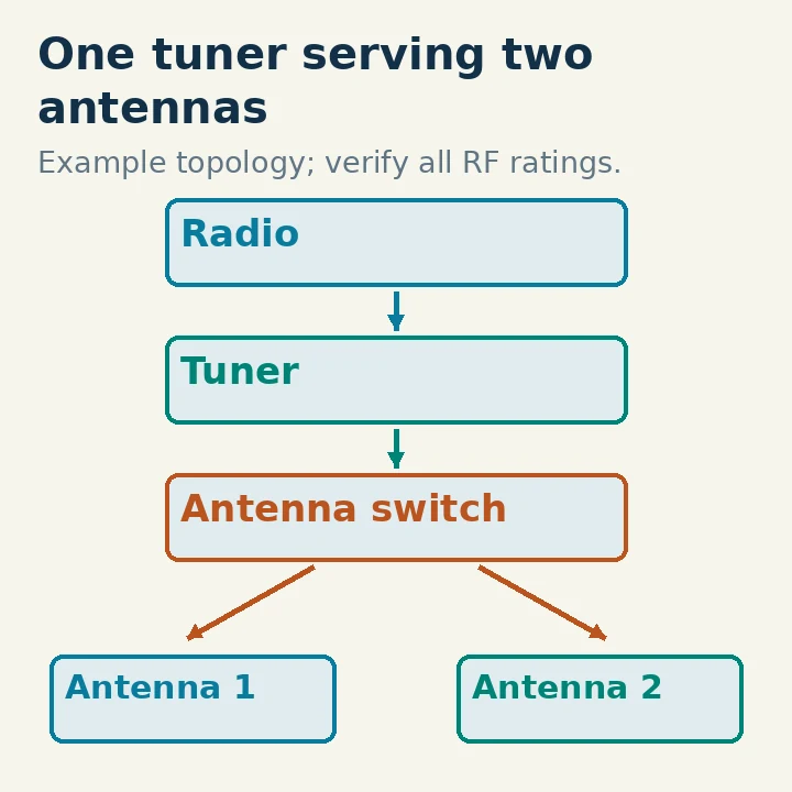
The switch on the antenna side of a tuner may see substantially different impedances and voltages from those at the transceiver's nominal 50-ohm connector. A successful match at the radio does not make every component after the tuner operate into 50 ohms. The switch, tuner, cable and connectors must tolerate the actual conditions. Avoid assuming a power rating measured into a matched load covers any high-SWR antenna system.
If the antennas have individual remote tuners, the station diagram changes. If an amplifier is present, the output switch must carry amplifier output rather than exciter power. Follow the equipment manuals for sequencing and protection. A receive-only switch or a small accessory relay should never be promoted to that job simply because its sockets fit.
Install It so the Labels Remain True
Stop transmission, turn the equipment off as appropriate for reconnection, and disconnect the existing feed line before rewiring. Secure the switch so cable weight cannot twist its connectors. Use strain relief and bends that suit the cable; do not use the switch as a support bracket for a hanging coax bundle.
Label the physical cables at both ends. A label saying “PORT 2” is useful only if there is a station diagram identifying port 2. Prefer operational names where possible. Put the dummy-load position somewhere unmistakable and identify the load's own frequency, power and time limits. A switch can route power to a load; it cannot enlarge that load's rating.
For a remote unit, follow the manual's mounting orientation, sealing, grounding and control-cable instructions. Keep water out of connections using an appropriate installation method. Do not treat a general indoor manual switch as weatherproof because it has a metal enclosure.
An unused-port grounding feature can be useful, but it is not a complete lightning protection system. An “OFF” position is not automatically a safe storm disconnection. The required protection depends on the building entry, bonding, grounding and equipment installation. Make the station's disconnection procedure explicit rather than assigning that responsibility to an undocumented knob position.
Commission the Switch Without Guessing
Start with all transmitters inhibited and the switch labels visible. If you can test the switch separately from equipment, check that its selected path agrees with the manual. A DC continuity test can reveal some wiring mistakes, but cannot verify RF isolation, loss or power handling. Internal protective components may also affect the expected DC reading.
Next, establish a known load. Connect a properly rated 50-ohm dummy load to one selected port and begin at low RF power within the limits of every component. Confirm that the radio sees a reasonable match. Stop transmitting before selecting the next port. Repeat only with an appropriate connected load or antenna on that path.
Keep these checks separate:
- Selection: Does the label identify the physically connected path?
- Match: Is the selected load acceptable at this frequency?
- Power handling: Are all components rated for the intended power and duty cycle?
- Isolation: Are connected unselected devices protected for this arrangement?
A low-power SWR check addresses only part of that list. A lossy or incorrectly routed system can still present a tolerable match. When available, an analyzer measurement of insertion loss or a comparison against a known through connection adds different evidence. Record the frequency and reference arrangement so later measurements can be compared fairly.
Use a Repeatable Changeover Sequence
Release PTT or stop the digital-mode transmission first. Disable VOX or automatic transmitting if it could restart during the change. Wait until transmission and any amplifier transmit indication have ended, then select the new antenna. Confirm the label, recall or establish the correct tuner setting, and begin with a low-power check before normal operation.
That conservative sequence avoids hot switching: changing contacts while RF is present. Unless the exact switch and installation are expressly designed and rated for hot switching, use a stopped-transmission procedure. A slow digital cycle can make it easy to forget that a computer is still scheduling another transmission; turn off its transmit-enable control as well as looking at the radio.
When checking two antennas on receive, switch reasonably close in time and keep receiver settings consistent. Fading and propagation can otherwise dominate the comparison. A louder signal may come with more noise, so assess readability rather than S-meter movement alone. Receive comparison also does not establish which antenna is safe to transmit into on that band.
Diagnose the Path Before Blaming the Antenna
If SWR suddenly rises after a change, stop and verify selection, cable identity and tuner state. Then inspect the switch connections and the selected feed line. If a direct connection works while the switched path does not, that narrows the fault to the added switch path, its connectors or the associated cabling; it does not yet identify one contact as the cause.
If reception changes when you touch the enclosure or move cables, investigate loose connectors and unwanted feed-line currents as well as the switch itself. If a remote switch selects the wrong antenna, confirm control voltage, cable continuity and the manufacturer's port mapping with RF disabled.
A successful installation ends with a station diagram, durable labels, known operating limits and a changeover procedure you can follow without improvising. That turns an antenna switch into a reliable station control rather than another ambiguous connection behind the desk.