PEP describes the power at the crest of a signal's modulation envelope; duty cycle describes how much of a stated time interval is spent transmitting. They answer different questions. A station can produce 100 W PEP while averaging much less RF power over a conversation, yet a long digital transmission can impose a demanding heat load even when transmissions occur only occasionally.
The practical consequence is that a radio, amplifier or filter's “100 W” label needs context. You need to know whether it describes peak envelope power, a continuous carrier, or a rating restricted to a particular mode and duty cycle. A low reading on the wrong meter is not permission to increase drive until every display says the same thing.
Start with the RF Envelope, Not a Single Spike
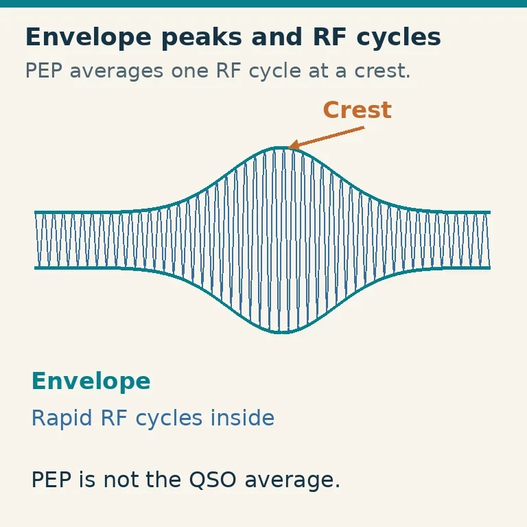
An RF signal oscillates many times per second. Its envelope traces the changing amplitude around those rapid oscillations. For an SSB voice signal, that outer shape changes with the speech waveform. For an unmodulated carrier, its amplitude is approximately constant while keyed on.
FCC §97.3(b)(9) defines peak envelope power in terms of the average power supplied to the antenna transmission line during one RF cycle at the modulation envelope's crest. Thus PEP is not the maximum instantaneous power within a single oscillation, and it is not the average over your entire transmission. This US definition was checked October 29, 2026.
Imagine a waveform with a large speech peak followed by quieter syllables and pauses. Its PEP follows the highest normal envelope crest, while a slower average-power reading reflects the quieter portions too. A peak-hold meter and an averaging meter can therefore disagree without either indicating that power has vanished.
Also keep the measurement point consistent. Transmitter output, power at the antenna after feed-line loss, and equivalent radiated power are different quantities. “100 W PEP at the radio connector” does not include an antenna's directional gain or prove 100 W reaches the antenna.
Define the Interval When You Quote Duty Cycle
The basic time calculation is:
Transmit duty cycle = time transmitting ÷ total observation time.
For an illustrative one-minute operating cycle, ten seconds transmitting and fifty seconds receiving is 10 ÷ 60 = 16.7%. Twenty seconds transmitting and forty receiving is 33.3%. State the observation interval: a transmitter can be continuously keyed during each ten-second burst even though its one-minute duty cycle is only 16.7%.
This is why two descriptions of duty cycle can appear to conflict. One concerns the fraction of a conversation spent transmitting. Another concerns how continuously the RF is present during a transmission. A constant-envelope digital burst can have essentially continuous RF while it is on, followed by a long receive interval. Neither description, by itself, establishes the equipment's permissible temperature.
Some manufacturers define ratings using specific transmit/receive sequences or named modes. Use their definitions rather than translating a marketing phrase into your own test. A duty-cycle rating also assumes the manufacturer's cooling, load and environmental conditions.
Compare a Carrier, CW and SSB Carefully
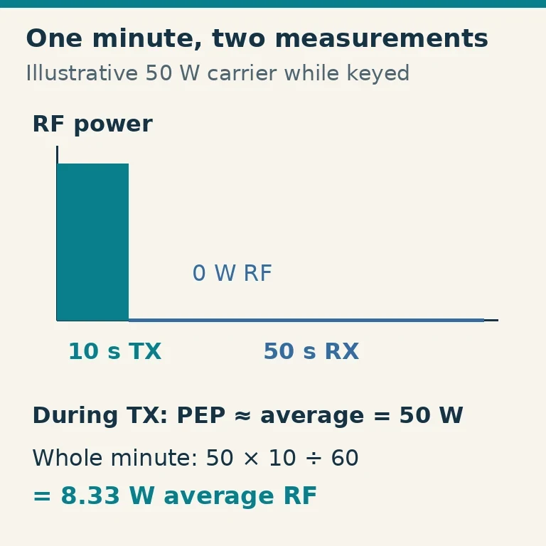
With an ideal constant-amplitude carrier, PEP and average RF power are approximately equal while the carrier is on. For example, a 50 W carrier produces about 50 W by either measure during a steady keyed interval. If it operates for ten seconds out of sixty, the average over that entire minute is about 50 × 10/60 = 8.33 W.
CW, or Morse radiotelegraphy, turns the carrier on and off to form elements. A stream of equal-length dots with equal internal spaces is keyed half of that stream's time. An illustrative 50 W on-state carrier then averages about 25 W during that dot stream. Character gaps, word gaps and listening make the average over a real exchange different again.
SSB speech does not stay at the envelope crest. Its average depends on speech characteristics, processing and pauses. There is no single conversion factor that turns every 100 W PEP SSB signal into a fixed average wattage. If an illustrative measurement showed 25 W average during your speaking periods, and you spoke for 40% of the total interval, the corresponding long-interval RF average would be 10 W. The 25 W is an assumed observation in this example, not a universal SSB specification.
Compression or processing can increase average power relative to PEP. That can improve some operating characteristics when correctly adjusted, but it can also increase heating or create distortion if overdriven. Follow the radio's actual microphone, processor and ALC instructions rather than chasing the highest average reading.
Understand Why a Low Transmit Percentage Can Still Run Hot
WSPR offers a useful example of two time scales. A standard WSPR transmission occupies about 110.6 seconds in a two-minute sequence. WSJT-X's Tx Pct chooses the average fraction of sequences devoted to transmission; it is not a control that reduces the RF power or converts each transmitted sequence into a short voice-like burst.
At a 20% selection, the station still needs to tolerate the full length and load of each selected transmission. Random scheduling also means a small number of observed cycles need not match the percentage exactly. A fan or filter cannot ignore a long burst just because the average across many cycles seems modest.
Check ratings for the radio, amplifier, tuner, filter and dummy load separately. For example, the AS-419 manual explicitly rates its particular 100 W filter system for 100% duty-cycle modes. That is a documented condition for that product, not a rule that all 100 W filters tolerate a continuous 100 W signal.
Airflow, ambient temperature, mismatch and installation can change the usable operating condition. Keep ventilation clear. Stop for overtemperature warnings, abnormal heating or unexpected protection behavior; do not disable a fan or protection circuit to preserve a desired output number.
Read the Meter You Actually Have
An ordinary RF wattmeter may average quickly varying speech rather than capture its peaks. A meter advertised for PEP needs the appropriate peak-detection behavior and, where specified, power for that circuitry. Read its manual to distinguish peak envelope mode from a slow pointer that simply happens to remain near a recent value.
A useful check is to identify the meter mode, measurement location and load before interpreting a number. If a test is required, follow the radio and meter manufacturers' procedure with a suitable 50-ohm load rated for the power and duration. Do not transmit a prolonged test carrier into a marginal load to obtain a reassuring reading.
| Reading or control | What it can tell you | What it does not establish |
|---|---|---|
| Properly measured PEP | Envelope-crest RF power | Long-term average heating in every component |
| Average RF wattmeter | Average over its response interval | Accurate speech PEP unless designed for it |
| Transmit-time percentage | Time allocated to transmission | RF power or safe continuous-mode rating |
| DC supply current | Electrical load drawn from the supply | RF output by itself |
The last distinction matters for portable power. DC input includes losses and the station's electronics. RF average watts cannot simply be substituted for battery consumption. Use actual input-current measurements or manufacturer specifications when calculating runtime.
Apply the Limits to the Complete Station
Start with the legal privileges for your band and license class, then apply the equipment's tighter limits. FCC §97.313 includes a general maximum and band/class-specific restrictions, and requires the minimum transmitter power needed for the communication. A headline PEP maximum is not a universal entitlement on every band.
Next, choose a mode and planned operating pattern. Identify the lowest applicable continuous-mode or duty-limited rating in the RF chain. Set drive and output using the equipment instructions, verify normal behavior and keep an eye on temperature and protection indications during a representative session.
Write your operating assumption in plain language: “This is my RF peak output, this is the mode, these are the longest bursts, and this is the rating that limits them.” That is more useful than treating PEP, average power and duty cycle as three competing versions of the same number.