Velocity factor is the speed of a wave in a transmission line divided by the speed of light in vacuum. A coaxial cable with a velocity factor of 0.66 carries the relevant wave at about 66% of that vacuum speed. At a given frequency, its wavelength inside the cable is also about 66% of the free-space wavelength.
That matters when calculating delay, cutting a quarter-wave coax section, comparing phase between feeders or converting an analyzer's reflection time into distance. It does not directly tell you the cable's attenuation, power rating or characteristic impedance.
Physical Length and Electrical Length Are Different
Physical length is what a tape measure reports. Electrical length describes how much phase a wave accumulates through that length at a specified frequency. A cable can be only a few meters long physically yet represent a substantial fraction of a wavelength electrically.
Use VF = v / c, where v is propagation speed and c is approximately 299,792,458 meters per second. For practical introductory calculations, c is often rounded to 300 million meters per second. Keep the same approximation throughout a calculation rather than mixing precise and rounded figures without explanation.
Wavelength in the cable is:
λcable = VF × c / f
For a 10 MHz signal, the rounded free-space wavelength is 30 meters. With VF = 0.66, wavelength in the cable is about 19.8 meters. A physical length of 4.95 meters is therefore approximately one quarter wavelength, or 90 degrees, in that cable at 10 MHz. It is not a quarter of the 30-meter free-space wavelength.
RigExpert's AA-55 ZOOM manual uses 0.66 for its RG-58 example and explicitly notes that manufacturing process and materials can change velocity factor. Treat a cable-family name as a starting point, not a substitute for the actual product's specification or a suitable measurement.
The Dielectric Affects Propagation
The insulating material between the center conductor and shield affects propagation speed. For a simplified low-loss line with nonmagnetic materials, velocity factor is related approximately to the inverse square root of the effective relative permittivity. A structure containing more air can have a different effective dielectric behavior from solid insulation.
Real cables also have geometry, frequency dependence, manufacturing tolerances and losses. Look up the exact cable variant, including suffixes that distinguish different constructions. Do not assign a foam cable's specification to a solid-dielectric version just because both are sold under a similar broad label.
Velocity factor is usually supplied as a decimal or percentage: 0.80 and 80% mean the same factor. A number such as 80 entered into software expecting 0.80 is a unit-format error, not a small tolerance. Check the input field's convention before trusting a calculated length.
A higher velocity factor means less delay per physical meter and a longer physical section for a given electrical length. It does not automatically mean lower loss or a better cable for every station. Diameter, attenuation at the operating frequency, shielding, connector suitability, flexibility and power handling remain separate decisions.
Calculate Delay and Phase
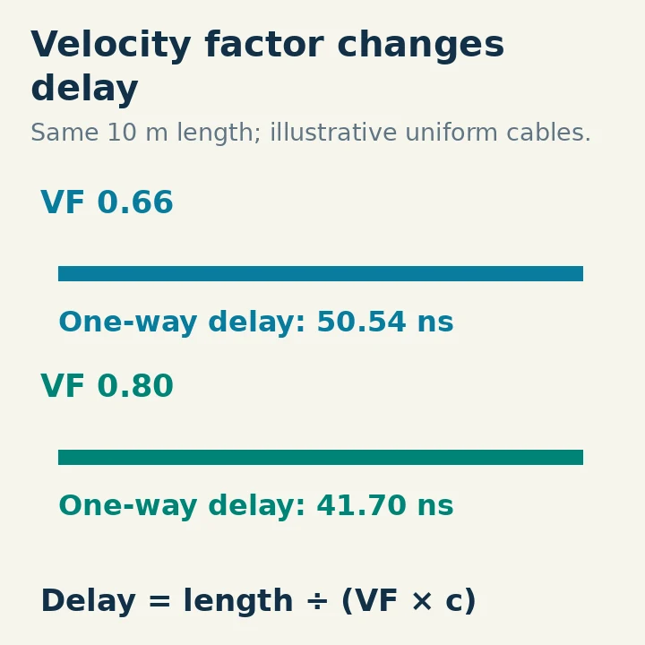
One-way delay through a uniform cable is:
t = L / (VF × c)
For a 10-meter cable with VF = 0.66, using the precise value of c gives about 50.54 nanoseconds one way. A reflected signal returning from the far end takes about 101.08 nanoseconds for the round trip. Those are different quantities, and confusing them creates a factor-of-two error in distance calculations.
Phase length at frequency f is 360° × f × t, with f in hertz and t in seconds. Equivalently, phase length is 360° × L / λcable. At 10 MHz, the 10-meter example is about 182 degrees long. At twice that frequency, the same idealized delay corresponds to twice the phase length.
For two otherwise identical cables, a physical length difference creates a phase difference. That matters in phased antenna arrays, divider systems and measurement interconnects. Equal visible lengths do not guarantee equal electrical lengths if the cables have different constructions, connectors or velocity factors.
For ordinary station coax feeding a well-matched antenna, you generally do not need to cut the cable to a special wavelength merely to make it work. Extra cable changes loss and delay and can transform the impedance observed with a mismatched load. It does not fix the antenna's feed-point mismatch by making the underlying load disappear.
Cut a Quarter-wave Section with the Right Factor
For a target quarter-wave electrical length:
Lquarter = VF × c / (4f)
At 10 MHz with c rounded to 300 million meters per second, a VF of 0.66 gives 4.95 meters. A hypothetical cable with VF = 0.80 gives 6.00 meters for the same electrical length. These are teaching values, not specifications for an unnamed retail cable.
A half-wave section is twice the quarter-wave physical length at the same frequency and velocity factor. A quarter-wave impedance transformer, stub or phasing section must also have the appropriate characteristic impedance and termination for its purpose. Getting electrical length right does not establish that the rest of the circuit design is correct.
Start slightly long when the construction and adjustment method permit trimming. Include the connectors and reference planes that will be part of the final assembly. Then measure the completed section using an appropriate analyzer method and trim in controlled small steps. Cutting too short can force a new assembly or an additional connector that changes the result again.
Do not treat the antenna's familiar free-space shortening formula as a coax velocity-factor measurement. End effects on a wire antenna and propagation inside a transmission line are different mechanisms. Use the cable formula for cable and the intended antenna method for the radiator.
Use an Analyzer to Estimate an Unknown Factor
To determine velocity factor, you need an independently known physical length and an electrical measurement. An analyzer cannot simultaneously discover both unknown length and unknown velocity factor from a single simple delay observation without additional information.
One method uses a known cable length with a defined open or short at the far end. The analyzer identifies an electrical-length condition over a frequency sweep. RigExpert's manual describes using the first quarter-wave resonance of an open-ended cable and the relevant half-wave conditions for a shorted cable. The correct resonance order and termination are essential; selecting a higher repetition as the first condition gives the wrong answer.
For a known open-ended cable whose first quarter-wave condition occurs at fquarter, the corresponding estimate is VF = 4 × L × fquarter / c. For example, a 5-meter section with that condition at 9.4 MHz gives approximately 0.627 using rounded c. That is a calculation from stated measurements, not proof that all cables of its general type have that factor.
Calibrate or otherwise account for test leads and adapters according to the instrument's method. Measure the physical section between the same effective reference planes used electrically. Avoid long unspecified jumpers between the calibrated port and the cable under test, because their delay can be mistaken for part of the cable.
Repeat the measurement and compare with any trustworthy manufacturer specification. A surprising value should prompt checks of units, resonance order, termination and reference plane before a conclusion about exotic cable properties. For precise phasing work, use a measurement technique appropriate to the frequency and required tolerance.
Why TDR Needs Velocity Factor
Time-domain reflectometry locates changes in a transmission line from reflected responses. A pulse instrument measures time directly; some antenna analyzers derive a time-domain display from a frequency sweep. Either way, the conversion from round-trip delay to distance requires propagation speed.
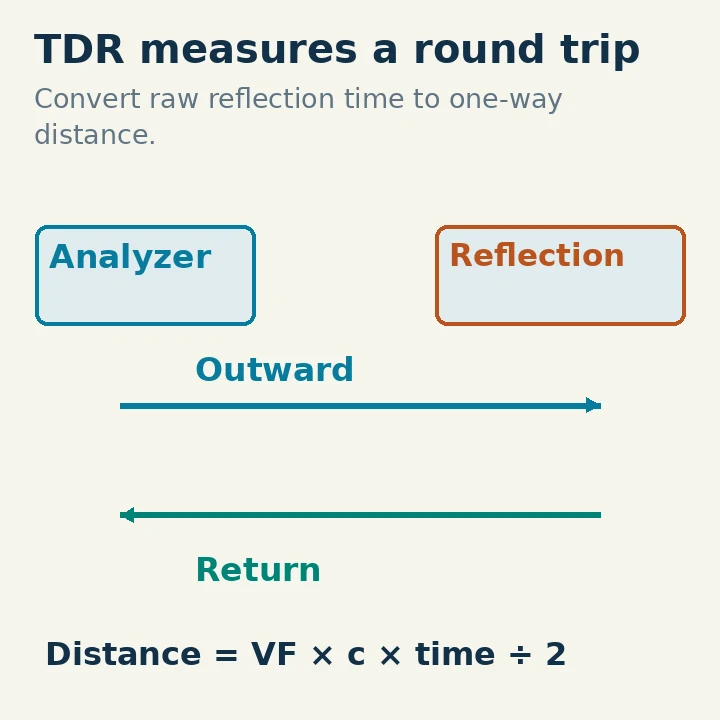
For a reflection arriving after round-trip time Δt:
Distance = VF × c × Δt / 2
The division by two accounts for travel to the discontinuity and back. A display may already perform this conversion. Do not halve its displayed distance a second time; understand whether you are looking at raw time or calculated distance.
Suppose the actual cable has VF = 0.66 but the instrument is set to 0.80. For the same measured reflection time, the displayed distance is about 0.80/0.66, or 1.21 times the true distance. A discontinuity 10 meters away can appear about 12.1 meters away. This is a settings error that directly affects where you start inspecting.
RigExpert's AntScope manual instructs users to set cable characteristic impedance and velocity factor for its TDR display. It also explains that a discontinuity response can help locate a problem without identifying its exact cause. A connector, junction, damaged section or intentional impedance change requires interpretation and inspection.
A line containing several cable types does not have one uniform speed throughout. Applying one factor to the entire path produces an approximate distance scale. Use the known sections and appropriate instrument facilities when accuracy matters. Connect analyzers only to a safe, nontransmitting system within the instrument's input limits.
Keep Velocity, Loss and Matching Separate
Velocity factor tells you propagation speed. Attenuation tells you how much signal diminishes along the cable at a stated frequency and length. Characteristic impedance describes the transmission-line voltage/current relationship. A 50-ohm cable does not become a different nominal impedance merely because its velocity factor differs from another 50-ohm design.
A low SWR reading is not a velocity-factor measurement. A perfectly matched cable can have substantial delay, and a mismatched cable can transform the impedance seen at its input as length changes. Record the actual quantity you measured rather than using “electrical quality” as a catch-all explanation.
For a useful station record, keep the exact cable type, physical length, specified or measured velocity factor, relevant frequency and measurement reference planes. Those details let you reproduce a phasing section, interpret a TDR distance or compare a replacement cable without confusing meters, degrees and nanoseconds.