A vertical antenna's radiation pattern describes where its radiated signal is stronger or weaker in different directions. The familiar “doughnut” picture is a useful starting point: a simple vertical can cover directions around the horizon while sending relatively little energy directly overhead. It does not mean the antenna transmits equally in every direction, and it does not guarantee a particular DX range.
To use a pattern sensibly, separate the view from above from the view across the horizon. Then check the antenna, ground and frequency assumptions behind the drawing.
Read the Two Views Separately
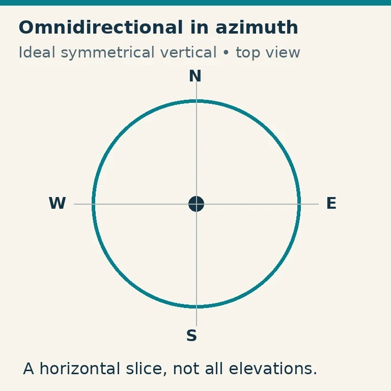
An azimuth pattern is a horizontal slice. Imagine looking down on the antenna and comparing compass directions at a chosen elevation angle. A symmetrical vertical over symmetrical surroundings can have an approximately circular azimuth pattern. That is the sense in which it is called omnidirectional.
An elevation pattern is a vertical slice through the antenna. It compares directions above the horizon: low angles toward distant terrain, steeper angles toward the sky and the zenith directly overhead. A circular azimuth plot says nothing about equal strength at all these elevations.
The three-dimensional pattern combines both. Rotating a simple vertical's elevation shape around its upright axis produces the broad doughnut-like image. Actual multiband antennas, ground conditions and nearby structures can distort that shape.
A pattern represents relative radiation, not the outline of a physical object or an RF safety boundary. A lobe is a region of stronger radiation. A null is a direction of reduced radiation. Neither is a sharp wall separating possible from impossible reception.
Begin with a Quarter-wave Monopole
A common HF vertical is approximately a quarter wavelength tall and uses a ground system. The upright radiator and its return-current environment work together; the metal rod alone is not the complete antenna.
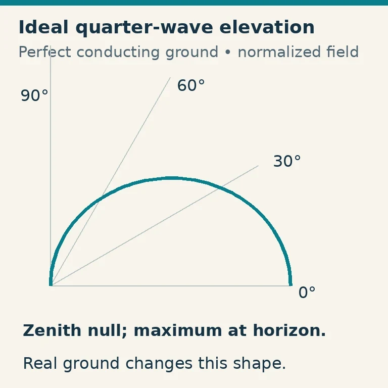
Over an ideal, perfectly conducting ground plane, the image principle makes the quarter-wave monopole resemble the upper half of a half-wave dipole. Its ideal upper-hemisphere pattern has maximum radiation along the horizon and a null on the vertical axis. Real ground and practical radial arrangements alter both efficiency and elevation shape.
The accompanying idealized elevation plot is normalized: its outer edge means the maximum for that model, not a measured number of watts or a claim of gain over another antenna. It assumes a thin quarter-wave radiator and perfect ground. A real installation need not peak exactly at the horizon.
IRTS's amateur study guide illustrates practical quarter-wave ground-plane patterns and discusses low-angle radiation, radials and counterpoises. Its particular example has its own assumptions; do not treat an angle from one example as a universal “vertical takeoff angle.”
Why Lower Angles Can Help with DX
For many HF skywave paths, useful energy leaves at a relatively low elevation angle, is refracted through the ionosphere and returns far away. A vertical that provides useful low-angle radiation can therefore suit long-distance contacts.
That advantage depends on the path. Ionospheric conditions, frequency, distance, terrain and the other station all matter. An antenna does not select one fixed launch angle and send every contact along it. Its pattern contains a range of angles, and the propagation path favors some of them at a particular time.
A high-angle regional HF path may favor a different antenna and height arrangement. That helps explain why a low horizontal antenna can work nearby stations well while a vertical hears distant stations more strongly. It is not evidence that one antenna is universally better.
Local VHF and UHF operation also involves polarization and line-of-sight geometry. Do not transfer every HF skywave explanation directly to a handheld-to-repeater link merely because both antennas are upright.
Understand What Radials Actually Change
Radials provide a return-current system and reduce loss associated with imperfect ground. ARRL's vertical-antenna introduction distinguishes radial and counterpoise arrangements as part of practical designs.
For ground-mounted HF verticals, a suitable radial system can improve efficiency by reducing ground loss. That does not mean each new radial creates another compass-direction beam. Symmetrical radials are intended to support the antenna system, not steer separate signals along the wires.
Elevated radials behave differently from a large set of wires on or near the soil. Their number, length, height and symmetry can affect resonance, feed impedance and pattern. Follow the chosen design instead of mixing a few dimensions from unrelated installations.
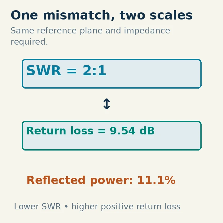
A good SWR does not prove efficient radiation. Loss can make an antenna easy to match while turning part of the transmitter's output into heat. Conversely, changing radials can alter the feed impedance and require adjustment even when the change reduces loss.
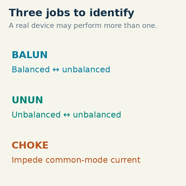
Coax is not automatically excluded from the antenna's RF current system. Unwanted common-mode current on the outside of a feedline can alter the pattern and bring RF into the station. Correct feed arrangement and an appropriate common-mode choke can help, but their placement and rating need to fit the installation.
Length and Frequency Change the Pattern
A quarter-wave description applies at a particular electrical length. A physically unchanged vertical becomes a different fraction of a wavelength as frequency changes. Its current distribution and elevation lobes can change accordingly.
A longer vertical can develop additional elevation lobes and nulls. “Longer” therefore does not always mean more useful low-angle radiation. A lobe at a steep angle may not help the DX path you want, even if the antenna radiates efficiently overall.
Loading coils, traps, matching networks and top loading allow compact or multiband operation, but they also affect current distribution and loss. A tuner achieving an acceptable match does not force every band to share the same pattern.
When reading a manufacturer's plot or modeling result, check which frequency it represents. A single picture next to a multiband antenna is not necessarily a full description of its behavior across every advertised band.
Nearby Objects Can Spoil the Symmetry
Buildings, metal fences, towers, other antennas and feedlines can reflect, absorb or reradiate energy. Sloping ground and different soil conditions around the installation can also make a real pattern differ from the ideal circle.
An installation beside a large metal structure may favor some directions and suppress others. Moving the antenna or changing its height can change those relationships. It is difficult to infer the entire three-dimensional pattern from one successful contact or a few reports.
If you model the antenna, include relevant conductors and realistic ground assumptions. Read the program's definitions of height, angle and gain. Modeling a perfectly conducting ground when the actual site has lossy soil can produce an attractive result with little predictive value.
ARRL's antenna-planning material explains why elevation, ground and antenna height belong in a path assessment. Its horizontal-antenna examples should be understood as examples of those antennas, not silently reused as measured vertical patterns.
Read a Polar Plot Without Misreading Its Scale
First identify the plane: azimuth or elevation. Then find the angular reference. Some elevation plots label the horizon as zero degrees; others use a different convention. Read the axes rather than assuming the top of every drawing means north.
Next inspect the radial scale. A normalized plot sets its maximum to a reference level. It shows shape, not absolute gain. A decibel scale can visually exaggerate small differences or make deep nulls look less dramatic depending on its range.
If gain is specified, check whether it is dBi, referenced to an isotropic radiator, or dBd, referenced to a dipole. Compare antennas at the same frequency, ground conditions, mounting arrangement and power reference. Otherwise the apparent difference may come from the comparison setup.
Finally, distinguish directivity from realized performance. Directional concentration, conductor and ground losses, mismatch and feedline loss can all affect the useful signal. A sharp-looking normalized lobe does not establish high efficiency.
Use the Pattern to Make a Station Decision
For broad HF DX coverage in several directions, a practical vertical may be attractive when you can install an effective ground system and keep surrounding conductors under control. For a specific regional path, compare its useful elevation angles with another suitable antenna rather than buying by the doughnut picture alone.
Evaluate changes with repeated observations on the same band and similar paths. Same-receiver reports, stable output and an A–B–A comparison are more informative than comparing one antenna at sunset with another the following morning.
Keep notes on frequency, antenna configuration, ground system and conditions. The useful question is whether the installation delivers more reliable signals for your actual contacts. Its radiation pattern helps explain those results, while the real station and changing propagation determine what you can work.