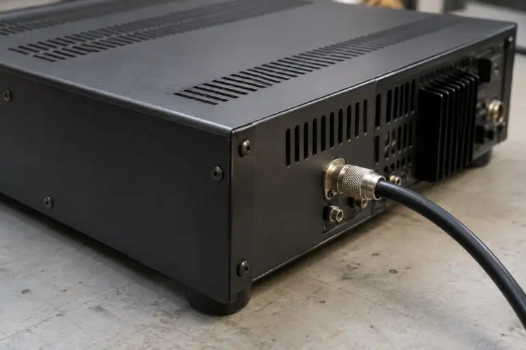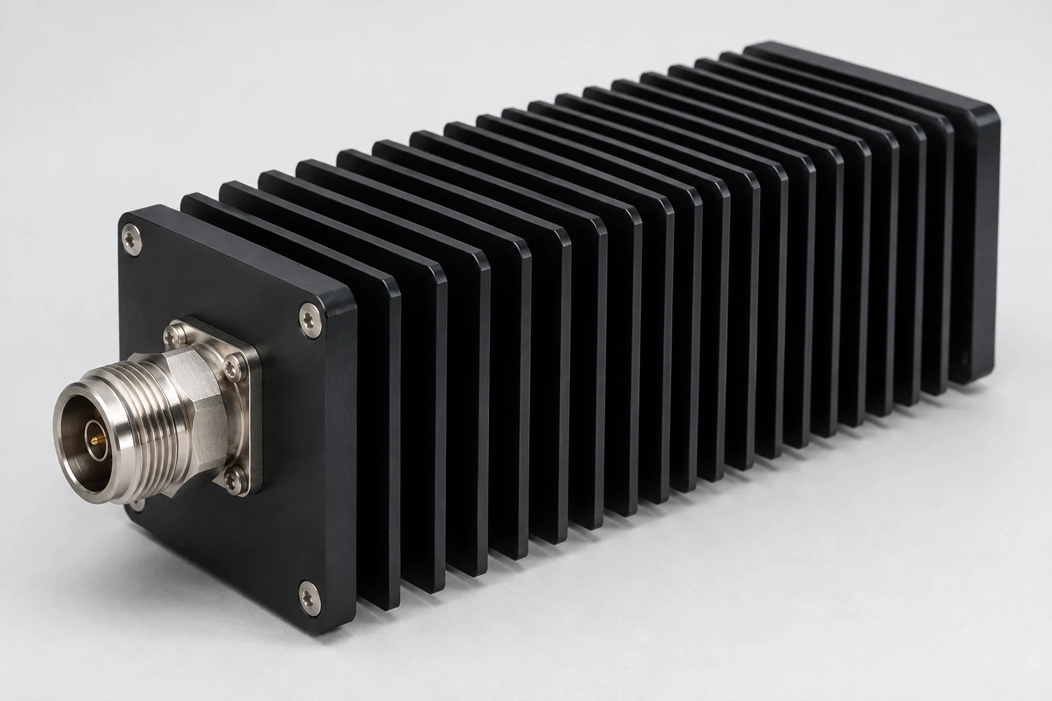
A dummy load replaces the antenna with a specified RF termination so you can make a limited transmitter-output check without using the antenna as the test load. For a beginner, the useful test is modest: confirm that the radio, connecting cable, measurement path and load are compatible; transmit briefly at a low documented output setting; then note what the indications show. A plausible output reading and low mismatch can support a conclusion about that connected bench path. They do not show that an antenna works, that your signal sounds good, or that the station meets every regulatory requirement.
Choose a Load and Measurement Path That Fit the Radio
Think of the setup as a path: radio RF output → suitable coaxial cable → suitable inline meter, if used → dummy load RF input. The load is the intended termination for this test, not an antenna. If you use an inline meter, its manual determines where it belongs, which way it faces and which connectors to use. The radio’s own display may also offer an indication, but it may not measure the same thing as an external meter.
Before connecting the path, identify the intended frequency, mode, radio output setting and approximate length of the proposed transmission. Those choices determine which specifications you need to check. Read the current instructions for the actual units you will use—not just a product name or a meter face—and verify all of the following:
- Impedance and frequency: Does the load suit the radio’s intended RF load and the operating frequency? Is the cable suitable for that frequency and connection? For example, the Icom IC-7300 manual calls for a 50 Ω antenna connection for the bands it identifies. That is a requirement to consider for that radio, not a claim that every radio or every dummy load has an exact 50 Ω specification.
- Power and time: Can the load, cable and any inline meter handle the planned output for the planned duration under their stated conditions? Check the radio’s applicable transmitting limits too. A short test is not permission to exceed a component’s rating, and a time-limited rating is not a continuous-keying rating.
- Connectors and measurement: Can you make the complete RF connection with suitable, specified cables and connectors? If you expect a watt reading, does the meter’s documentation support that measurement at your frequency and setting? Check its range and measurement direction before relying on an indication.
- Cooling and recovery: Does the load require a fan, clear ventilation or a cooldown period? Determine what its instructions require before keying, including what to do between transmissions.
The Palstar DL2K manual illustrates why reading the rating matters more than reading the largest number visible. It identifies an SO-239 coaxial input from the transceiver and separately labels a 12 V, 500 mA supply connection. The low-voltage connection is for fan power; it is not the RF input. The manual also warns that although its meter scale reaches 5000 W, its stated maximum dissipation is 2000 W for up to one minute with the fan on. The scale cannot raise that limit. This is a rating-reading example, not a suggestion to buy that load or run a beginner’s check anywhere near its limit.
Nor is “up to one minute” a recommended transmit time. It is a ceiling under the conditions stated in that manual excerpt; it does not establish continuous-duty operation or a safe duration at every output level, ambient condition or cooling state. The quoted information does not establish the DL2K’s impedance tolerance, frequency limits or a thermal-chart allowance. Consult the current manual for the particular unit in front of you rather than filling those gaps with assumptions.
If the specifications for any part of the path are missing, incompatible or unclear, do not transmit into the assembled setup. Resolve the uncertainty with the documentation or help from a qualified operator. The workable plan is the one that fits every component’s applicable limits, not merely the radio’s output setting or the load’s meter scale. For a first check, there is no need to seek maximum output: choose the radio’s lowest documented setting that can give a useful indication with the measurement equipment you have.
Connect and Configure the Unkeyed Bench Setup
Leave the radio unkeyed before changing any RF connection. Power it down as appropriate to its instructions, then identify its proper RF output and the load’s labeled RF input. Connect those points with suitably specified coax, placing an inline meter in the position and direction its manual requires if you are using one. Check that the connector arrangement is correct at each end. Do not put an RF cable into a load’s low-voltage fan-power socket.
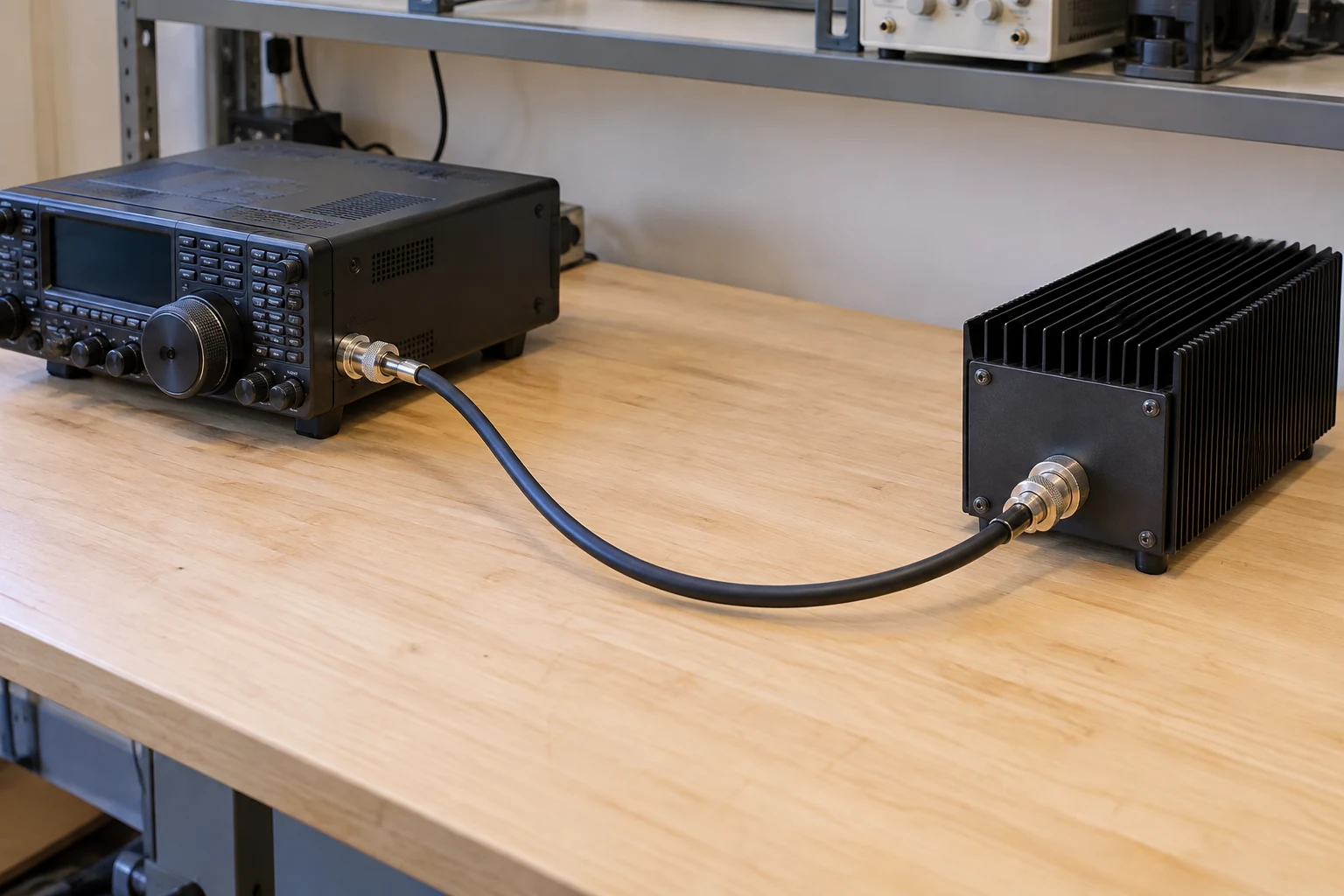
Set up the load’s required cooling before transmission. Provide any specified fan supply, keep ventilation openings clear and confirm the arrangement against the actual load’s instructions. For the DL2K example, Palstar says that with its fan switch in ON, the fan runs continuously while power is supplied. That describes this unit’s stated switch behavior; another load may operate differently. If you cannot confirm that required cooling is working, leave the transmitter unkeyed.
Set the radio to a frequency and mode supported by the documented radio-to-load path. Select its lowest documented useful output for this check, rather than treating full output as a test requirement. If an inline meter is fitted, use its instructions to choose a suitable range and measurement direction. Decide in advance which display you will watch for output and which, if available, you will watch for mismatch.
Keep the displays’ meanings separate. The IC-7300 manual describes its Po indication as relative RF output power, so Po is not, by itself, a calibrated watt measurement. A suitably specified external meter may provide a different measurement according to its own instructions. Write down the chosen settings if they will be hard to recall afterward; you will need them to make sense of the result.
Before any keying, a properly licensed control operator must be in control, and the station configuration and intended transmission must be authorized. Receiving or setting up a cable path is not the same as having authority to transmit. If that condition is uncertain, resolve it before proceeding rather than using the dummy load as a reason to key.
Make One Short, Controlled Output Check
First, make an unkeyed readiness check. Confirm that the complete path is connected as documented, required cooling is operating, and the meter is set correctly. Recheck that your selected frequency, mode, low output and proposed brief keying fit the actual radio, load, cable and meter instructions. Include any power or cooldown restrictions that apply to your equipment. The DL2K manual’s 2000 W, up-to-one-minute rating with its fan on is not an instruction to transmit for a minute, and it supplies no general allowance for continuous keying.
With those conditions met, key briefly at the selected output and watch the appropriate output and mismatch indications. You are looking for an indication that makes sense for this particular configuration, not trying to reach a target number invented for the test. If using an external meter, interpret its indication using its documented function, range and direction. If watching an IC-7300’s Po display, treat movement as a relative output indication rather than reading it as calibrated watts.
A plausible output indication suggests that the connected path is showing transmitter output during this brief check. A suitably low mismatch indication suggests that, at the measured point and frequency, the radio is not seeing an unexpectedly poor match in this setup. Neither observation identifies the cause of every possible fault elsewhere in the station. The IC-7300 manual describes its SWR display as showing the antenna’s SWR at the frequency; with a load fitted instead of an antenna, interpret what you see in light of that changed connection and any inline meter’s own instructions. Do not promise yourself a particular SWR or power reading without a documented basis for expecting it.
Stop transmitting immediately if you see an unexpected mismatch or alarm, notice a smell, or detect concerning heating. Return to receive before touching RF connectors. Leave the path unkeyed while you compare the settings and connections with the manuals, check the cooling arrangements and decide whether the equipment needs further help. Do not try to diagnose an RF connector by loosening or disconnecting it during transmission.
An absent or surprising indication is also a reason to pause, not to increase output automatically. For example, an output display that does not move might reflect a setting, a meter-range or direction choice, a connection problem, or equipment requiring attention. That list is a set of possibilities, not a diagnosis from the display. Review the documented configuration while unkeyed; repeat a brief check only after you have a supported reason to believe the setup is correct and within its limits.
End the Test and Decide What the Readings Establish
Return the radio to receive when the brief observation is complete. Follow the actual equipment’s cooldown instructions, even if the test seemed uneventful. Change or disconnect RF connections only while unkeyed and powered down as appropriate to the equipment instructions. Keep any cooling that the load requires available for as long as its instructions call for it; finishing the transmission does not override a cooldown requirement.
Make a short record while the details are fresh. Note the frequency and mode, selected radio output setting, approximate keying duration, whether required cooling was operating, and what the external meter or radio displays indicated. Record an alarm, unexpected mismatch or other abnormal sign too. This is not about giving a rough indication false precision. It preserves the conditions behind it: a later reading is useful for comparison only if you know what configuration produced each observation. A change of mode, output setting, meter range or connection can change what the comparison means.
The positive verdict is deliberately narrow. If the equipment was compatible and operated within its instructions, cooling was in place, no abnormal signs appeared, and the indications were plausible, you have support for saying that the configured radio-to-load bench path produced an output indication under those particular conditions. You have not established a universal output figure for the radio at every setting or for another connection path. If the only output indication was the IC-7300’s Po display, describe it as relative; do not convert it into a measured number of watts.
If the readings were absent, unexpected or inconsistent, the verdict is different: the check has not yet given you a dependable positive result. Leave the setup unkeyed and resolve the configuration, documentation or equipment question before another attempt. You need not decide that the transmitter itself has failed merely because a display was blank, just as you should not declare it healthy merely because a display moved. An unresolved alarm, heating concern or mismatch is a stop condition, not a prompt to continue keying for a clearer reading.
Finally, keep the boundary between the load test and the rest of the station clear. Because the antenna has been replaced, this check does not demonstrate antenna radiation or the performance of the feed line after you reconnect it. An output or mismatch indication here does not test receiver performance, voice modulation quality, spectral purity or the absence of leakage. It also does not establish complete FCC compliance. Those are different questions requiring appropriate checks; a normal indication into a dummy load cannot answer them.
The useful result is a documented, low-output bench check made within the actual ratings, with a conclusion limited to the path and conditions you tested. That is worthwhile information before further station work—but it is not a certificate for the whole station.