A ham radio power supply needs enough continuous DC current capacity for the exact radio’s documented requirement or transmit demand, at a voltage the radio accepts. There is no dependable amp number to assign from RF output wattage alone. Start with the radio’s manual or manufacturer specifications, then compare the relevant amp figure with the supply’s continuous rating—not just a larger number printed elsewhere on its label. Confirm voltage and connections before choosing a manufactured supply. ARRL likewise directs buyers to a radio’s specifications and to a supply’s continuous current rating.
What the Amp Rating Measures
Two specifications answer different questions. Transmit current consumption describes what a manufacturer says its radio draws under a stated transmit condition. Supply current capacity describes how much current a power supply is rated to make available. A supply rated for more amps does not, by that rating alone, make a radio draw more; the question for selection is whether the supply can meet the radio’s documented demand or the manufacturer’s explicit supply instruction.
An RF output-power figure answers neither question by itself. Dividing a radio’s RF output watts by its nominal DC supply voltage does not establish its DC transmit draw: it treats power delivered as an RF signal as though it were the same quantity as electrical power taken from the supply. For a beginner, the useful distinction is simply RF output is not the DC-input specification. Look for a manufacturer’s transmit-current entry or supply-capability instruction instead of calculating amps from the number of watts on the radio’s description.
ARRL gives broad context by saying that a transceiver with a maximum output of 100 W will require about 25 A at 13.8 V. That is useful as a warning against sizing a supply from RF watts divided by voltage. It is not an instruction to buy a 25 A supply for every radio advertised as 100 W, nor a substitute for the exact model’s documentation.
The wording of that documentation matters. A listed transmit consumption, such as “21 A at 100 W output,” reports a current under the stated condition. An instruction to use a supply “capable of supplying at least” a stated current sets a minimum supply capability. Those are related figures, but they are not interchangeable measurements. In either case, the supply’s relevant comparison figure is its continuous current rating. ARRL explicitly identifies that rating as the one to look at; its separate discussion of intermittent ratings explains why a prominent maximum-amp number may not answer the same question. The actual label comparison comes after identifying which sort of radio specification you have.
Why Two 100 W Radios Do Not Give the Same Sizing Instruction
Icom’s IC-7300 specifications list 21 A transmit consumption at 100 W output. Icom separately specifies a 13.8 V DC ±15% power-supply requirement for that model. The first entry supplies a stated transmit-demand figure; the second supplies the radio’s documented voltage requirement. Neither entry is a rule for another manufacturer’s radio.
Yaesu frames the pertinent FT-991A amp figure differently. In the DC IN Jack section on page 27 of its English operating manual, Yaesu instructs owners to use a DC supply capable of supplying at least 23 A at 13.8 V DC. That is an explicit minimum supply-capability instruction. It should not be relabeled as a measurement of the radio’s transmit consumption, or compared with Icom’s 21 A as though both manufacturers had published the same kind of test result.
Yaesu’s Japanese specification page separately identifies an FT-991A HF/50 MHz 100 W version and lists 13.8 V DC ±15% as its supply voltage specification. Those statements give model/version and voltage context; the at-least-23 A supply instruction above comes from the English manual. No operating condition for an FT-991A current-consumption figure needs to be inferred from the Japanese page to make this comparison.
Together, the examples show why the words beside an amp number are as important as the number. The IC-7300 entry tells a reader its stated draw at a specified RF output. The FT-991A manual tells a reader a minimum capacity for the supply connected to that radio. A buyer can use each for its own documented purpose without pretending they establish a common consumption figure or a universal requirement for 100 W equipment. Even matching RF-output descriptions would not resolve an unfamiliar model’s DC requirement. Its own documentation must do that job.
Choose a Continuous Rating from the Radio’s Documentation
First identify the radio precisely enough to find its own manual or manufacturer specification. Record the voltage requirement and copy the meaning of the current entry along with its number: is it transmit consumption under a named condition, or an instruction that the supply must provide at least a certain current? ARRL advises reading the transceiver’s specifications before buying; the IC-7300 and FT-991A documents illustrate why that lookup is more useful than starting with an output-wattage calculation.
Next read the candidate supply’s rating as carefully. ARRL notes that supplies can have both continuous and intermittent (ICS) current capacities and says to use the continuous figure for this comparison. A supply advertised with a large intermittent rating but no identifiable continuous DC rating leaves the capacity decision open. The intermittent figure cannot simply be substituted for the continuous one.
Consider an illustrative comparison, not a report of tested equipment. Icom lists the IC-7300’s transmit consumption as 21 A at 100 W output. Suppose one candidate supply is labeled 20 A continuous / 30 A intermittent, while another is labeled 25 A continuous. The first candidate’s 30 A intermittent number does not fix the fact that its 20 A continuous rating is below the radio’s published 21 A transmit figure. On that comparison, it is not the suitable choice for that documented transmit condition. The second candidate’s 25 A continuous rating exceeds the published figure, so it passes this particular current-capacity comparison—if its rating applies to the DC output being considered. That favorable comparison is not yet a complete compatibility verdict. Icom’s 21 A entry and the distinction between continuous and intermittent ratings are documented; both candidate labels here are hypothetical.
The distinction also prevents a different mistake: treating a documented consumption figure as though Icom had explicitly commanded a particular minimum supply rating. The 21 A number gives a condition to cover when comparing capacities. It does not, by itself, specify a fixed percentage of extra capacity to buy. For the FT-991A, by contrast, Yaesu has already given an at-least-23 A supply-capability instruction, so a candidate’s continuous rating must meet that stated minimum.
A shared supply adds another question. If an accessory will draw from the same DC supply, its separately documented demand must be accounted for alongside the radio’s relevant demand; current reserved for one connected load is not available twice. This is a capacity-planning inference, not a claim that either cited radio has a particular accessory load. For example, a hypothetical 25 A continuous supply that passes the IC-7300-only comparison cannot automatically be approved for the radio plus an accessory of unknown draw. Obtain the accessory’s relevant specification and the supply’s continuous rating before deciding whether their combined demand fits. No fixed headroom percentage can replace those missing facts.
The practical outcome of this section is a conditional one: a known, adequate continuous rating can establish that the current comparison passes for documented loads. An intermittent-only label, an unidentified radio-current figure, or an unknown shared load cannot establish it. Voltage and physical compatibility still have their own checks.
Check Compatibility Beyond the Amp Number
A compact, owner-filled comparison keeps unlike specifications from getting mixed together:
| Item to record | What the entry must answer |
|---|---|
| Exact radio model | Which radio’s documentation governs this choice? |
| Radio’s DC voltage requirement | What voltage does that documentation specify? |
| Radio’s amp figure and its wording | Is it stated transmit consumption or a minimum supply instruction, and under what stated condition? |
| Candidate supply’s DC output voltage | Does its documented output suit the radio’s requirement? |
| Candidate supply’s continuous current rating | Does it cover the applicable radio figure and any documented shared loads? |
| Connection details | Do the exact radio and supply documents establish compatible polarity, connector and any specified cable arrangement? |
This is a comparison record, not a universal set of acceptable numbers. For example, Icom specifies 13.8 V DC ±15% for the IC-7300. Use that as an IC-7300 specification, not as permission to apply the same tolerance to a different model. Yaesu’s Japanese specification page also states 13.8 V DC ±15% for the FT-991A, while its English manual’s DC IN instruction specifies a supply capable of at least 23 A at 13.8 V DC. Keep each model’s voltage and current statements attached to its own documentation.
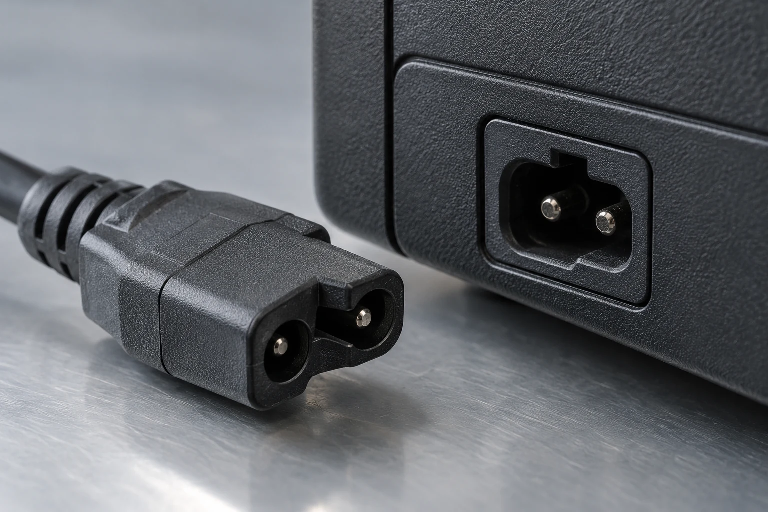
Amps and voltage do not establish that a supply can be connected correctly. Check the exact radio manual for polarity, connector and any specified cable arrangement, and compare those requirements with the candidate supply’s documentation. The FT-991A English manual, for instance, describes its DC IN jack as the supply connection and instructs use of the supplied DC cable. That is a model-specific instruction, not a reason to assume the same arrangement for another radio. If the documentation does not settle a connection detail, pause the choice rather than guessing or treating matching voltage and amps as proof of compatibility.
For a switching supply, interference is another separate consideration. ARRL advises looking for models that claim low RFI, or radio-frequency interference. A low-RFI claim is therefore a feature worth investigating; it is not evidence here that a particular supply is noiseless, independently tested, or suitable in every station. Do not allow an attractive interference claim to stand in for a missing voltage, connection or continuous-current specification.
A purchase decision should remain on hold when the radio’s required voltage or relevant current cannot be identified, when a supply offers only an intermittent current number, or when the connection documents are missing or conflicting. The comparison cannot be completed by borrowing another model’s tolerance or guessing what an amp label means. This article does not provide a wiring or mains-work procedure; the aim is to determine whether the documented manufactured-supply specifications make a defensible match.
Turn the Specifications Into a Purchase Decision
Take the FT-991A as a worked hypothetical selection, not a product recommendation. Its English manual calls for a DC supply capable of at least 23 A at 13.8 V DC. Suppose a manufactured candidate is documented as providing 25 A continuous at the required DC voltage. On the stated figures, its continuous capacity is above Yaesu’s minimum, so the radio-only supply-capacity comparison passes. Unlike a comparison built only from an RF wattage figure, this verdict rests on an explicit instruction in the radio manual. The 25 A candidate is imaginary; Yaesu’s at-least-23 A instruction is the documented fact.
That verdict has limits. Before selecting that candidate, its actual DC output specification still needs to match the radio’s voltage requirement; the connection documentation must settle polarity, connector and Yaesu’s specified cable arrangement. Any other equipment intended to share the supply brings its own documented demand into the capacity decision. If the candidate is a switching supply, ARRL’s low-RFI advice gives the buyer an interference feature to investigate, not a guarantee of quiet operation. Passing the 23 A comparison alone answers none of those remaining questions.
Now consider an unfamiliar radio advertised by its RF output power, alongside a seller’s supply labeled only with an impressive intermittent amp rating. Neither number supplies the missing model-specific DC demand or the supply’s continuous capacity. The decision is defer selection, not assign that radio the IC-7300’s 21 A, the FT-991A’s at-least-23 A, or ARRL’s broad “about 25 A” example. Find the exact radio documentation and a continuous DC rating for the candidate first. Icom, Yaesu and ARRL attach their respective figures to different statements; none makes its number universal.
The amp answer, then, comes from the exact model’s documentation. A supply becomes a defensible choice when its continuous capacity covers the applicable documented figure and its voltage and connections are compatible—not merely when its largest advertised amp number looks high enough.