To check a radio’s DC connector polarity, first find the exact model’s required voltage and contact layout in its manual. Then, with the radio disconnected, measure the external supply’s output only if you can reach its contacts without risking a short. Compare the measured voltage and polarity with the manual before connecting anything. A familiar-looking barrel plug is not proof that its center is positive, and wire color cannot establish what an assembled cable delivers—especially if an adapter or repair has changed it.
Identify the Radio’s Required Contacts and Connector View
Start with the exact radio model, its manual, and the supply connection you intend to use. Identify the cable and any adapter between the supply and radio; the connector you will measure must be the one whose contacts will ultimately supply the radio. Keep the radio disconnected while you work out the requirements. If you cannot identify the radio, the intended cable, or the manual that applies to it, stop rather than using a similar model’s instructions.
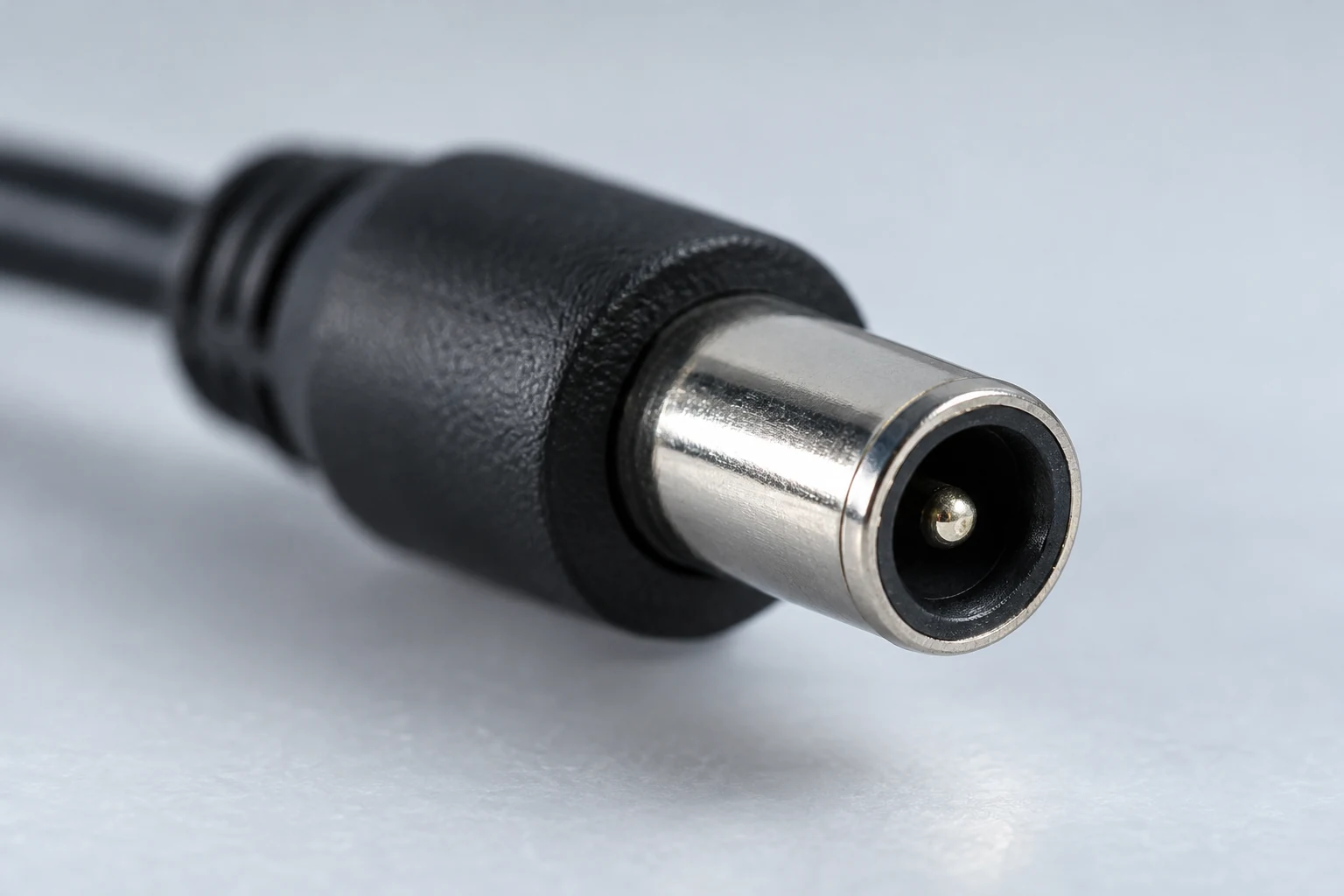
Find the manual’s DC input information and record two separate requirements: the permitted input voltage and which physical input contact must be positive relative to which contact must be negative. For a barrel connector, that might mean identifying the center contact and outer sleeve. For a keyed connector, use the manual’s contact identifiers and the connector’s physical features to distinguish the contacts. Do not substitute the connector’s shape for a contact map: a barrel plug is not automatically center-positive, and two connectors that look alike need not have the same wiring.
Check the viewpoint of every connector drawing before transferring its labels to the part in your hand. Is the illustration looking into the radio’s socket, at the mating face of the cable plug, or from the cable end? A mating-face view and a rear view can place a contact on opposite sides of a drawing even though both depict the same connector. Orient the actual connector using the key, notch, or other identifiable feature shown in the manual, then name its contacts in words. For example, write “outer sleeve: negative” only if you have established that from this radio’s documentation—not because it seems customary. If the drawing’s viewpoint or the contact identities remain uncertain, do not guess or try a connection to find out.
Make the same distinction on the supply side. The radio manual tells you what the radio requires; it does not, by itself, prove what voltage or polarity an existing supply cable delivers. A wire’s color or an old label may help you locate a cable, but neither verifies the polarity at its output connector. An adapter or previous repair makes that distinction especially important. Your eventual comparison must refer to the contacts on the actual plug that will mate with the radio, not merely to markings elsewhere on the lead.
The Icom IC-7300 illustrates why model-specific instructions matter. Its manual specifies regulated 13.8 V DC ±15% through the supplied DC power cable, says to confirm the transceiver is off before connecting that cable, and prohibits reversing its polarity . Those statements are requirements for that example, not a universal voltage for radios and not, on their own, a pinout for an unidentified connector. For your radio, use its own voltage specification and an unambiguous contact diagram. If either is missing, seek the correct documentation or qualified help before proceeding.
Measure the Supply Output Without Bridging Its Contacts
Measure only a safely accessible external low-voltage DC output, with the radio disconnected. Do not open the supply or probe mains wiring. Do not insert meter tips into a connector if a tip could bridge adjacent contacts, and do not proceed with damaged leads, exposed conductors you cannot handle safely, or an uncertain contact layout. A voltage check is optional when access is unsafe: the correct next step is qualified assistance, not a smaller improvised probe or a trial connection.
Before energizing the output, consult your actual meter and probe manuals and check that their ratings and condition suit the measurement. Select DC voltage, not current. Fluke’s digital-multimeter instructions place the black probe in COM and the red probe in the V Ω voltage input . Check the markings on your meter rather than assuming its sockets have the same layout. Fluke also warns that placing probes in A or mA inputs and then measuring a voltage creates a short in the measurement circuit . If a lead is still plugged into a current input from an earlier task, correct the setup before approaching the supply.
With the external output not energized, identify the two supply-side contacts you intend to measure. Name them by physical location or by a reliably established connector contact identifier—not by wire color alone. Decide where each probe could rest separately and steadily. On a barrel plug, for instance, reaching the center contact may be difficult without a tip touching the sleeve; on a compact keyed plug, contacts may be too close together for your probes. If you cannot plan a placement that keeps the tips from slipping together or touching neighboring metal, stop. A reading is not worth shorting the output.
Only if stable, nonbridging access is possible should you energize the external output for the measurement. Keep the radio disconnected. Place the red probe on one identified contact and the black probe on the other, without changing the meter’s input connections. Read both the voltage magnitude and its displayed sign, and record which physical contact each probe touched. The number alone does not tell you which contact is positive unless you retain that probe-to-contact mapping.
On a correctly configured polarity-detecting digital meter, a negative sign means the contact under the red probe is at a lower potential than the one under the black probe. Fluke notes that a negative symbol appears when the probes touch opposite-polarity terminals . In practical terms, a positive reading means the red-probed contact is at higher potential; a negative reading means the black-probed contact is at higher potential. This interpretation assumes the meter is set up for DC voltage and the contacts have been identified correctly.
For a hypothetical example, suppose you can safely probe a barrel plug and record “red: center; black: sleeve; +12.1 V.” That reading identifies the center as positive relative to the sleeve, with a measured magnitude of 12.1 V. If instead the display reads “−12.1 V” with the probes on those same contacts, the center is negative relative to the sleeve. These examples interpret readings; they do not say whether 12.1 V is suitable for any particular radio. That decision requires the exact radio’s input specification.
Swapping the probes would change the sign of either displayed reading, but it would not change the cable’s polarity. If you reverse the probes to check your interpretation, the written contact assignments must change too; otherwise a sign recorded by itself can be misleading. There is no need to reverse probes simply to make a negative sign disappear. What matters is which identified contact is actually positive at the plug that would connect to the radio.
If the reading is unstable, unexpected, or difficult to obtain without moving a tip near another contact, stop and de-energize the output. Do not reposition slipping probes on an energized connector, attempt a live repair, or treat a fleeting number as verification. An unreliable measurement leaves the output unverified. When the reading is complete, de-energize the output before removing the probes.
| What to record | Your entry |
|---|---|
| Radio model and manual | Record the exact model and manual used |
| Radio’s required positive and negative contacts | Name both physical contacts as identified from the manual |
| Radio’s specified DC input range | Record the range for this model |
| Supply contact touched by the red probe | Name the contact, not just its wire color |
| Supply contact touched by the black probe | Name the contact, not just its wire color |
| Measured DC voltage | Record the magnitude and displayed sign |
Compare the Result and Decide Whether to Connect
Bring the two contact maps together: the radio manual’s required positive and negative input contacts, and the supply plug contacts you identified while measuring. First confirm how the plug mates with the socket, using the documented connector view rather than a guess based on left and right in a drawing. Then ask whether the plug contact that will meet the radio’s required positive contact actually measured positive relative to the contact that will meet its required negative contact.
Next compare the measured voltage magnitude with the permitted DC input range for that exact radio. A correct sign at the correct contacts does not make an out-of-range voltage acceptable; likewise, an acceptable number does not excuse reversed polarity. The IC-7300’s 13.8 V DC ±15% supplied-cable specification is an example of a model-specific requirement, not a substitute for looking up the range of another radio .
The decision is conditional:
- Polarity and voltage both match: You can move on to the remaining connection checks and follow your radio manual’s instructions. This measurement supports proceeding; it does not certify the entire power setup.
- Polarity is reversed or voltage is outside the specified range: Do not connect the radio. Use the correct documented supply and cable, or seek qualified help to resolve the mismatch.
- Contacts, diagram view, access, or reading are ambiguous: Do not connect on the strength of an assumption. Obtain the correct documentation or qualified assistance.
- The connector or lead is damaged: Do not use a plausible meter reading to justify connecting it. Have the connection assessed or replaced appropriately.
Before making any radio connection, ensure the external output is de-energized and remove the meter probes. Keep the radio off and follow its manual’s connection sequence; the IC-7300 manual specifically instructs users to confirm that transceiver is off before connecting its DC power cable . Do not bypass a fuse, open a supply, or treat swapping meter probes as a fix for a reversed lead. Those actions do not turn an unsuitable output into a verified one.
Finally, be precise about what passed. A safe, stable measurement can establish the unloaded output voltage and polarity at the contacts you reached. It cannot by itself establish adequate current capacity, proper fusing, connector fit, acceptable ripple, or performance when the radio draws power. If those remaining requirements are unknown, resolve them using the radio and supply documentation or qualified help before relying on the setup.
Continue reading
Keep learning about radio