The Short Answer: Choose for the Site, Not an Assumed Winner
Start with the space and supports you can use. A Resonant end-fed half-wave is a half-wave wire fed at one end; favor it when placing a feed point there is easier than reaching the middle, provided the wire and its return path fit. A Center-fed dipole has two legs fed at their junction; favor it when you can support both legs and route the feed line from the center. A Quarter-wave ground-plane vertical pairs an upright radiator with a radial ground plane; favor it when horizontal radiator span is scarce but there is room for that radial footprint.
These are choices about layout, not interchangeable labels for any end-fed wire, vertical dipole, or multiband trapped antenna. The easiest feed point may still leave an awkward wire route; the smallest radiator span may demand space at ground level instead. None of those site advantages establishes a same-condition gain or DX winner.
What Each Build Needs at the Feed Point and on the Ground
The three builds put the feed point—and the work around it—in different places. A resonant end-fed half-wave feeds a half-wave wire at one end; a center-fed dipole feeds two equal quarter-wave sections where they meet; a quarter-wave ground-plane vertical uses an upright quarter-wave element with radials as its RF return system. The feed point is where the antenna connects to the feed line running back toward the radio. These are specific architectures, not interchangeable names for any end-fed wire or upright antenna. Their layouts determine where the connection, support and return path must fit before a particular construction project is chosen.
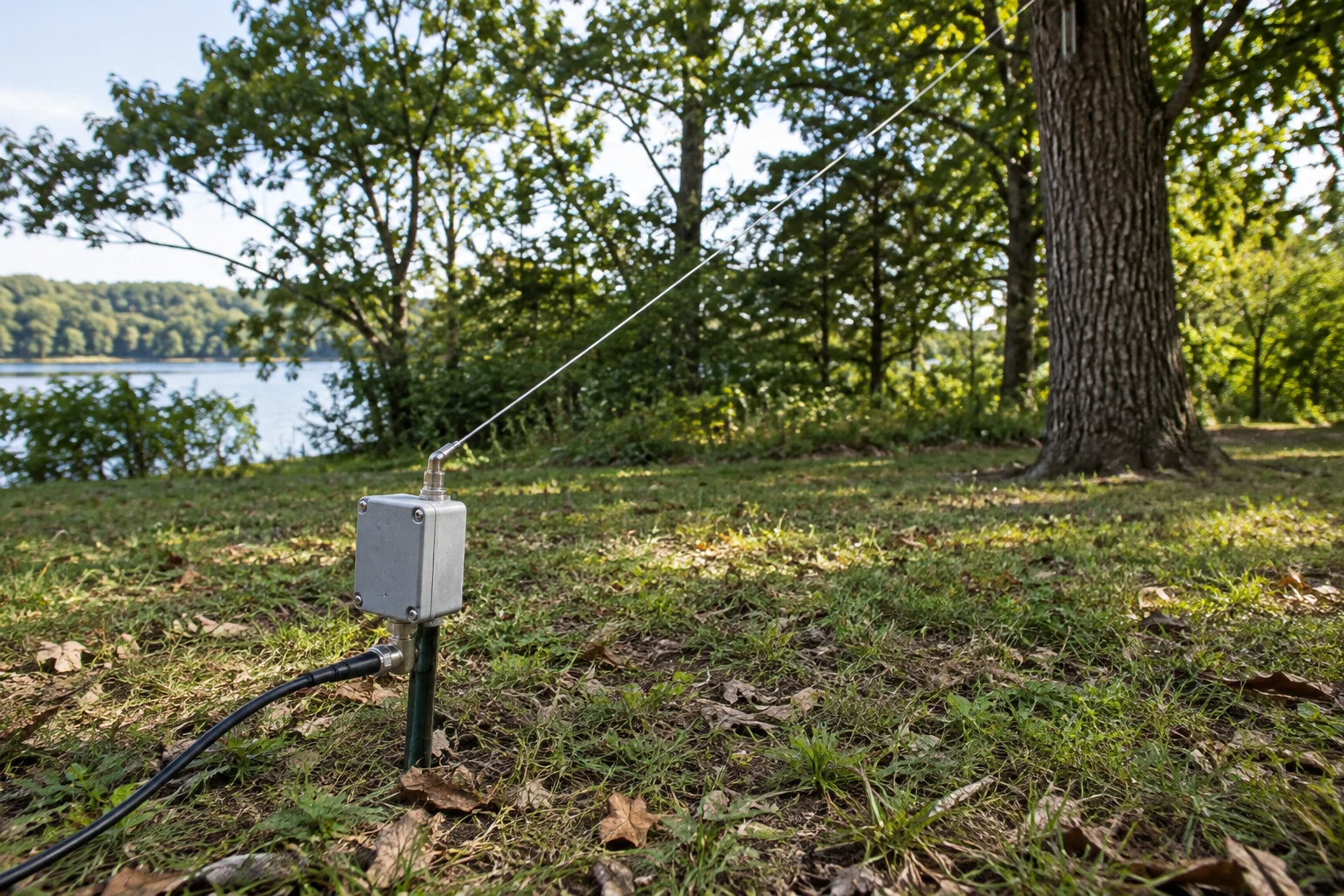
For the resonant end-fed half-wave, the practical attraction is that the feed connection can be placed at an accessible end rather than at the middle of a suspended wire. That does not make the feed electrically simple. AA5TB reports practical end impedances around 1,800–5,000 ohms; ARRL’s four-band EFHW project uses a 49:1 matching network to adapt its high end impedance. A builder following that example needs room at the fed end for the matching assembly and its connections, plus a route for the half-wave wire and coaxial feed line. The 49:1 network describes that project, not a required component specification for every end-fed half-wave. Nor should the matching assembly be omitted from a materials plan merely because the wire itself has only one feed end.
The less visible part of that layout is the RF return path. ARRL’s EFHW kit provides separate connections for the antenna wire, counterpoise and coax. AA5TB notes that an EFHW field installation with no visible counterpoise may instead use the feed line or radio as the return path. Thus, “one-end feed” does not mean “no other electrical path to consider.” If the matching unit sits beside a portable operating position, its counterpoise connection and the coax route are part of the build plan, not details to discover after the wire is up. The kit illustrates one way to provide those connections; its exact parts are not a requirement of the architecture. For site planning, ask where the end-feed assembly can go and what will provide the return path, rather than counting only the visible radiator.
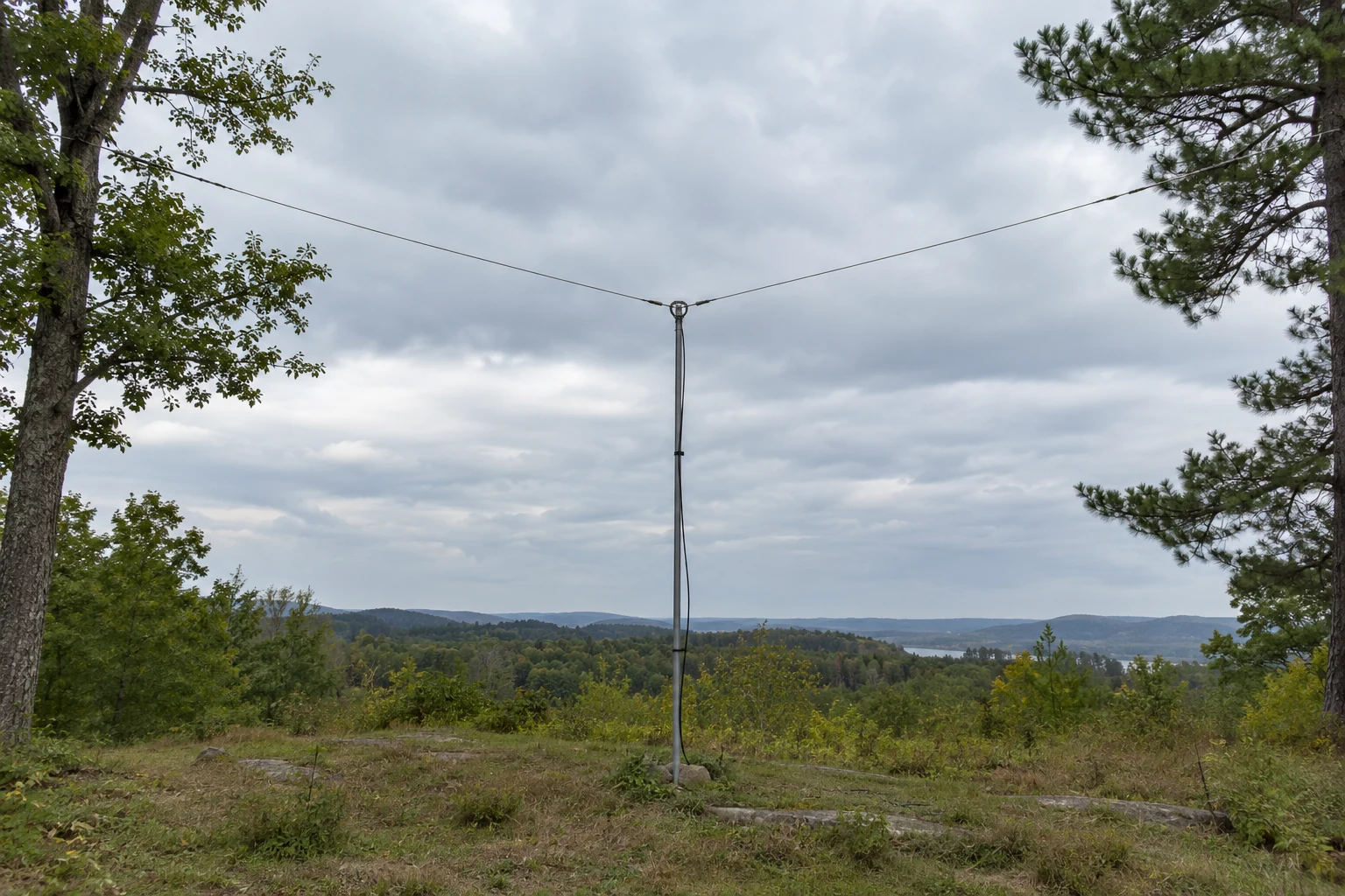
A center-fed dipole makes the radiator and feed arrangement more apparent: two equal quarter-wave wire sections meet at the feed point. ARRL gives 468 ÷ frequency in MHz as a starting total length in feet for a simple half-wave dipole. That number helps estimate whether two legs will fit; it is a starting dimension, not a suspension plan. Unlike the end-fed layout, the dipole needs a workable position for the center connection and a feed-line route from that position. Its two wire legs must also be accommodated, whether they extend outward or slope down from a raised center. A site with suitable end positions but no practical way to place or reach the center feed may therefore be less straightforward than its available wire span suggests.
ARRL’s classic multiband dipole is one concrete example of those support and routing demands. It suspends the two end insulators with rope and can be arranged as an inverted V by raising the center and sloping both legs downward. Its center is fed with ladder line—two parallel conductors—to a balun; ARRL instructs builders of that project to route the ladder line downward, perpendicular to the dipole wires, and keep it off the ground. Picture a center support with room for both sloping legs but a feed line that would have to cross one of them: the wire shape may fit while the documented ladder-line route does not. Conversely, space below the center makes that particular route easier to plan. This is an example of a multiband dipole build, not a requirement that every center-fed dipole use ladder line, that balun arrangement or the same supports. The routing instructions matter when choosing that project, rather than defining every possible dipole feed arrangement.
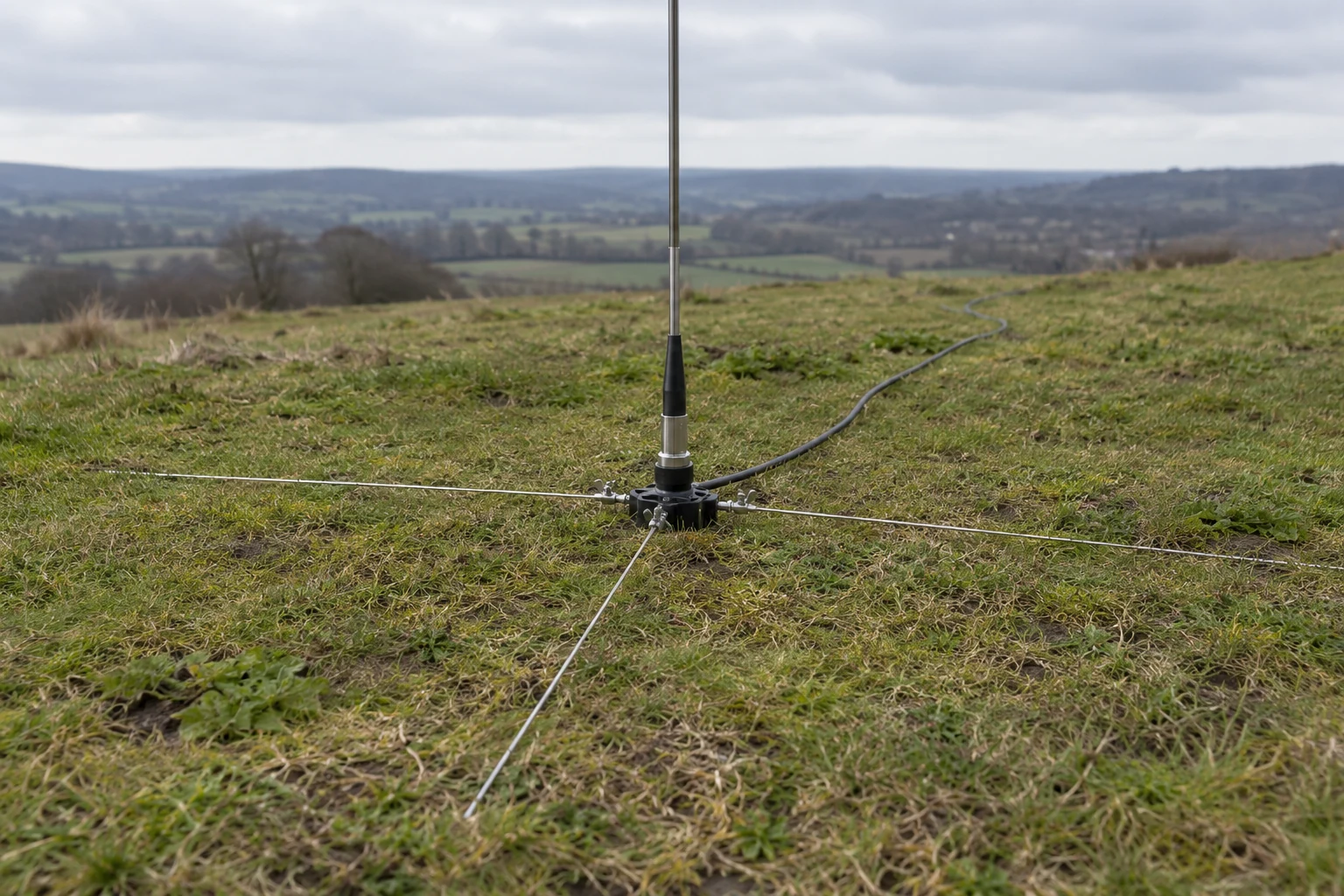
The quarter-wave ground-plane vertical shifts the main radiator upright. ARRL gives 234 ÷ frequency in MHz feet as a starting length for its quarter-wave element. Compared with laying out two dipole legs, the upright element takes little horizontal radiator space. But the element is only one part of the footprint: ARRL describes the radial or counterpoise system as the vertical’s other electrical half and notes that radials can provide a moderately low-loss RF return. The feed point therefore needs a connection arrangement for both the upright element and the radial system, with the feed line routed away from that area. A clear spot for a mast or other upright support is not, by itself, a clear spot for the complete antenna. This is a ground-plane vertical with a planned radial return, not a vertical dipole with two upright radiator halves.
That radial footprint can be substantial in a portable example: WB0ISG’s linked vertical uses sixteen 10-foot radials. Those figures show what one builder chose, not a radial count or length imposed on every quarter-wave ground-plane vertical. They do make the site-planning tradeoff concrete. An open patch that cannot accommodate a long horizontal radiator might accommodate an upright element, yet the ground around it still has to hold the chosen radial layout. Before selecting this layout for its compact-looking radiator, account for the space occupied by its other electrical half.
The three parts lists consequently start in different places. The EFHW calls for a half-wave wire, an end-feed matching arrangement and an accounted-for return path. The dipole calls for two wire legs, a center connection, supports and a feed-line route from that center; the ARRL ladder-line build adds its particular routing and balun arrangement. The ground-plane vertical calls for an upright element and support, a feed connection and a radial system. These distinctions do not establish which antenna will perform best at a given site. They identify the components and paths that must be feasible before a seemingly convenient feed location or small radiator footprint becomes a workable build.
Which Bands and Deployment Footprints Fit Your Site?
Band coverage is a property of a particular build and its matching arrangement, not a promise made by an antenna’s shape. The Resonant end-fed half-wave in ARRL’s named kit is designed for 10, 15, 20 and 40 meters; its coax connection sits at one end of the half-wave wire. Those documented bands describe that kit, not every end-fed half-wave. If your intended band is outside that list, you need a design and matching arrangement specified for it rather than assuming the kit’s coverage extends further.
The Center-fed dipole presents a different band decision. ARRL’s classic dipole has two equal wire legs joined at the center. Its illustrated multiband version uses ladder line, a balun and a tuner—one way to pursue several bands, not equipment required for every dipole. ARRL says that version needs a tuner in most cases, that changing bands may require readjusting it, and that an acceptable SWR may not be possible on every band. If quick band changes matter to you, account for that adjustment and the possibility that one desired band will not work acceptably in the illustrated arrangement.
For the Quarter-wave ground-plane vertical, WB0ISG’s portable linked example changes the resonant element length by opening or closing links for bands from 10 through 20 meters. That is a more hands-on band-changing approach than leaving one element setting in place: select the appropriate link configuration for the band you intend to use. Its documented range does not establish coverage on bands outside 10 through 20 meters; those would call for a separately specified element arrangement.
Now put those band plans onto the site. An end-fed feed connection can be placed at one end of its wire, while a dipole’s feed connection is at the junction of its two legs. Imagine a permitted location with one useful support some distance from the operating position but no convenient route for a feed line to the middle of two wire legs. The end-fed layout may be easier to place there. At a site where a central support and feed-line route are convenient and the two legs have room to extend away from it, the dipole’s layout may instead be straightforward. Neither feed location tells you that the antenna will cover a particular set of bands: that still depends on the build and, for the illustrated multiband dipole, the available tuning range.
A ground-plane vertical trades horizontal radiator span for a different footprint. ARRL notes that verticals use little horizontal radiator space but still need space for radials. It also cautions that a traditional vertical without a decent radial system may be a poorer choice than a dipole. Thus a narrow spot that cannot take two long wire legs might accommodate the upright element yet still fail to accommodate its radial layout. Conversely, a broad usable patch around a mast can make the vertical’s footprint workable even where overhead wire routes are awkward. Count the radial area as occupied space, not as space saved merely because the radiator is upright.
In a park, the distinction between physical room and an acceptable footprint matters for all three layouts. POTA asks operators to keep a station footprint acceptable to park staff and notes that many parks restrict wires or ropes in trees and stakes in the ground. A one-end feed does not by itself make an end-fed wire unobtrusive if its route crosses a shared area. A dipole’s two legs can spread into places other visitors use, while a vertical’s radials can occupy ground around an otherwise compact upright. Treat tree attachments and stakes as possible constraints on each proposed layout, rather than assuming that “portable” means the same installation methods are available at every park.
The practical comparison is therefore two overlapping maps: the bands documented for the build you plan to make, and the space its wire, feed route or radials would occupy. ARRL’s four-band end-fed kit, its tuner-fed multiband dipole example, and WB0ISG’s linked vertical demonstrate three distinct ways to approach band changes; none establishes universal band coverage for its architecture. Sketch each candidate’s full footprint against the available operating area before settling on a band-changing scheme. That makes the tradeoff visible: convenient feeding may still require a long wire route, multiband tuning may add adjustments, and a short horizontal radiator footprint may still require substantial ground space.
Verify the Intended Bands Before Normal Transmission
Check the site before checking the antenna. At a park, confirm that its actual rules permit any stakes or tree use your setup requires; do not assume that permission follows from being allowed to operate there. Place the antenna, feed line and any ground-level parts where they will not block other park users. POTA calls for an unobstructed station footprint. Keep every antenna and feed line clear of electrical power lines: ARRL warns against placing either over or under them. If you cannot identify a safe placement—or cannot tell whether a proposed attachment or stake is permitted—stop rather than trying to make the layout fit.
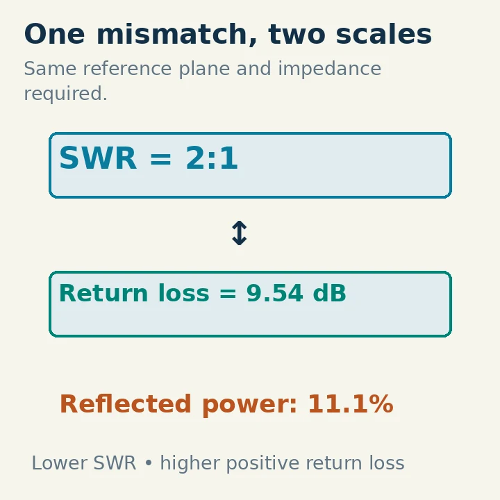
Once the setup is in its intended position, check it on the bands you plan to use before normal transmission. SWR (standing-wave ratio) is a measure used to assess how well the antenna system matches the transmitter through its feed line; an antenna analyzer can check an antenna without making a normal on-air transmission. Treat a reading as a reason to investigate or adjust the build, not as permission to overlook an unsafe placement. If changing the setup moves a wire, support or feed line, repeat the clearance and footprint check before measuring again.
- Resonant end-fed half-wave: For its EFHW kit, ARRL instructs builders to make the initial SWR check at low power. It recommends trying different antenna configurations before trimming the wire, then removing only a couple of inches at a time when trimming is needed. That order matters in a portable setup: first check the wire as deployed, then see whether a workable change in its position improves the result. Avoid making an irreversible cut simply because the first arrangement gives an unsatisfactory reading. Recheck after each change, and keep the wire and feed line clear as you move them. The low-power check and trimming sequence here are instructions from a particular kit, not a claim that every end-fed build uses identical hardware.
- Center-fed dipole: Check the match with an SWR meter on the intended band. ARRL notes that dipole element length normally needs adjustment for the best impedance match. If you adjust the two legs, measure again in the arrangement you intend to use; do not treat an untested length change as a finished repair. A different case is ARRL’s ladder-line multiband dipole project: its instructions call for adjusting tuner controls to the lowest SWR on each intended band. For that project, a satisfactory check on one band does not replace the tuner check on another. The project’s tuner procedure is not a requirement for every center-fed dipole.
- Quarter-wave ground-plane vertical: If yours is a linked portable build, verify the section selected for a band before moving on to the next section. In WB0ISG’s linked-vertical example, the builder checks a section with an analyzer and trims it gradually to resonance before adding the next band section. That staged approach makes it possible to tell which section you are adjusting. Recheck the assembled setup after changes to its deployment; do not assume that a previously measured section settles the check for every linked configuration. This is a procedure for a linked example, not an instruction to add links to every quarter-wave vertical.
Use the measurements to guide small, identifiable changes rather than changing several things at once. If a check remains unsatisfactory, pause and inspect the relevant build and its intended configuration before further trimming or tuning. Do not move wires toward a power line to improve a reading; ARRL’s prohibition on routing antennas or feed lines over or under electrical lines still applies during adjustment. If the problem calls for work near electrical infrastructure, an uncertain support installation, or troubleshooting beyond what you can safely identify, stop and seek help from a qualified operator or installer. Normal transmission can wait until the intended-band checks, site permissions, clear footprint and electrical clearance all hold for the finished arrangement.
Make the Final Choice from Your Constraints
If you can place the feed point conveniently at one end but not in the middle of a wire span, choose the Resonant end-fed half-wave—provided its intended bands and return-path footprint work for that site. Its placement advantage matters less if the matching arrangement or feed-line route becomes awkward.
If you have room for two wire legs, a workable center support, and a feed-line route from that center, choose the Center-fed dipole. Weigh any changes you would need for your intended bands against the effort of arranging those supports.
If horizontal radiator span is the limiting factor, choose the Quarter-wave ground-plane vertical only when you can accommodate its radials. A compact-looking radiator does not eliminate the space needed at its base.
Build the option whose bands, matching effort, supports, feed line, and return-path footprint all fit together—not merely the one with the easiest single component to install. Commit only after it passes the site and verification checks above.