Start with the Station’s Requirements
Choose the feed line—the cable between the radio and antenna—around the station, not around a familiar cable name. First identify the bands you will use, the length the cable must actually travel, your transmitter power, and the antenna’s standing-wave ratio (SWR), a measure of how closely the antenna presents the intended load. Those inputs frame the choice of a nominal 50-ohm coaxial cable and connector assembly.
Start with impedance. ARRL says commonly used amateur coax is nominally 50 ohms and transceivers are designed around 50 ohms. For an antenna designed to present 50 ohms, it recommends a 50-ohm coax path . Check the intended radio and antenna specifications before comparing cable products: a cable’s advertised size or low-loss figure cannot establish whether it belongs in that path. If the antenna is not intended to present 50 ohms, identify its matching requirements rather than assuming that a different coax label will solve the problem.
Then describe the installation as it will be used. A portable setup, a vehicle installation and a fixed station may call for different lengths and routes. Record the distance the cable will follow rather than only the straight-line distance to the antenna. Note every frequency on which you expect to transmit, not just the band you use most. Treat transmitter power and antenna SWR as station requirements too, rather than assuming the cable choice can be made from distance alone. If the antenna’s expected SWR is unknown, mark it for verification; do not silently treat it as a matched load.
At this stage, the goal is a useful specification, not a product winner: a nominal 50-ohm feed-line path for the intended radio and antenna, with the operating bands, routed length, power and antenna SWR written down. Include the connection points at both ends so the eventual connectors can be checked for compatibility. That gives the later loss, routing and assembly decisions a defined job to solve.
Calculate Loss for Your Band and Run Length
Coaxial feed-line loss is commonly expressed in decibels (dB) per 100 feet. That makes a published figure a starting point, not the loss of every installation: the cable type, operating frequency and actual run length all matter. ARRL notes that loss at a given frequency varies by feed-line type. Measure the route the cable will follow, rather than using the straight-line distance to the antenna, then use a loss figure published for the frequency you intend to operate.
At 50 MHz, three specific 50-ohm cables offer a useful matched-loss comparison. Belden 8240, identified as RG-58, has 2.5 dB nominal attenuation per 100 feet; Times LMR-240 lists 1.7 dB typical; and Times LMR-400 lists 0.9 dB typical. These are figures for the named models, not for every cable sold as RG-58 or under an LMR-branded name. Times specifies that its LMR-240 and LMR-400 attenuation figures assume a voltage standing wave ratio (VSWR) of 1.0—a matched line—and a 25°C ambient temperature.
To estimate loss for a different length at the same frequency, multiply the per-100-foot figure by the run length divided by 100. For example, a 25-foot run of Belden 8240 at the cited 50-MHz rate works out to about 0.63 dB; LMR-240 works out to about 0.43 dB; and LMR-400 works out to about 0.23 dB. The difference between Belden 8240 and LMR-400 is roughly 0.4 dB for that short run, versus 1.6 dB between their published figures over 100 feet. That calculation shows why the lowest-loss cable on paper need not be the deciding factor for a short route, while the same per-100-foot gap becomes more consequential as the route grows.
Keep the length and frequency identical when comparing candidates. A per-100-foot specification is a common basis for comparison, not a requirement to buy 100 feet; conversely, comparing one cable’s 25-foot estimate with another cable’s 100-foot specification would obscure the cable choice. If your route is longer than expected, redo the calculation with its measured length before deciding whether the difference in loss warrants a different cable. The arithmetic estimates attenuation in the cable under the cited conditions, not the performance of the entire installed assembly.
The band can change the decision just as much as the length. ARRL says a short, low-SWR mobile run can use RG-58 acceptably, but calls a 100-foot RG-58 run at about 440 MHz a poor choice. Those are contrasting situations, not a blanket endorsement or rejection of RG-58. A compact mobile installation has little distance over which loss can accumulate; a long UHF route needs its own frequency-specific figures. Likewise, the 50-MHz figures above establish a common comparison point, not a promise that the cables will retain the same loss gap—or even the same ranking—on another band or with a mismatched antenna.
Before buying for a band other than 50 MHz, look up the relevant attenuation figure for the exact cable model and calculate it for your measured length. Do not substitute the 50-MHz rate merely because it makes the arithmetic convenient. If the antenna presents appreciable mismatch, treat the resulting number as a matched-line estimate rather than a prediction of installed loss: the cited Times tables assume VSWR 1.0.
Check Whether the Cable Fits the Route and Power Demands
A lower-loss cable is not useful if the installed run must be bent more tightly than its specification allows. Map the route as well as measuring its length: note fixed corners separately from places where the cable will move whenever equipment is set up, packed away or repositioned. An installation bend radius describes a bend made while placing the cable; a repeated bend radius is the relevant figure where that bend will be made again and again.
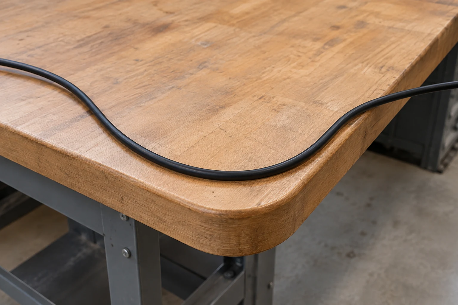
The distinction changes the choice. Times LMR-240 specifies a 0.75-inch installation radius but a 2.5-inch repeated-bend radius. Times LMR-400 specifies 1.00 inch for installation and 4.0 inches for repeated bending . Suppose a portable setup repeatedly bends its feed line around a 3-inch-radius turn. That turn clears LMR-240’s published repeated-bend figure but not LMR-400’s, even if LMR-400 looks more attractive on loss. Widening that turn could make LMR-400 feasible; if the route cannot change, its loss advantage does not resolve the bend problem. Do not treat the smaller installation number as permission for repeated flexing.
Belden 8240 specifies a 1.9-inch minimum installation bend radius . That rules out a tighter fixed corner as routed, but it does not establish what radius is suitable for repeated movement. If the cable will be coiled and redeployed or flexed at a moving station, resolve that question for the intended use rather than substituting its installation figure. A different route may be simpler than choosing cable solely to fit one sharp turn.
Weight matters at supports and at points where a run could pull on an assembly. Published bulk-cable weights are 26 lb per 1,000 ft for Belden 8240, 0.034 lb per foot for Times LMR-240 and 0.068 lb per foot for Times LMR-400 . Over 100 ft, those figures work out to approximately 2.6, 3.4 and 6.8 lb of cable, respectively, before connectors or other installation hardware. That difference may be unimportant on a well-supported fixed route but consequential for a portable reel or a run that would otherwise hang from its termination. Support the cable for the route you actually plan; do not ask the connector to serve as the support.
Power specifications need a different kind of care. At 50 MHz, Belden 8240 lists 530 W maximum power, while the Times tables list 1.15 kW average power for LMR-240 and 2.57 kW average power for LMR-400 . These are published figures with different labels, not interchangeable promises that one complete feed-line assembly will safely handle a given transmitter output. They can help identify which datasheets deserve closer attention, but they cannot settle a purchase by themselves.
For the proposed installation, check how the manufacturer’s power figure applies to the operating frequency and conditions, including ambient temperature, antenna VSWR and the installed cable. Account for the connectors as part of the assembly rather than assuming the bulk-cable number covers them. If the power case is unclear, do not compensate by picking the largest number in the comparison: establish the applicable limits before committing to the route or cable.
| Cable | Loss at 50 MHz, per 100 ft | Installation bend radius | Repeated bend radius | Weight | Published power at 50 MHz |
|---|---|---|---|---|---|
| Belden 8240 (RG-58) | 2.5 dB nominal | 1.9 in minimum | Check for the intended movement | 26 lb per 1,000 ft | 530 W maximum |
| Times LMR-240 | 1.7 dB typical | 0.75 in | 2.5 in | 0.034 lb/ft | 1.15 kW average |
| Times LMR-400 | 0.9 dB typical | 1.00 in | 4.0 in | 0.068 lb/ft | 2.57 kW average |
Specify the Complete Outdoor-ready Assembly
The cable route determines more than how much coax to order. If part of the run will be exposed to weather, specify the cable variant for that exposure rather than treating the bulk cable’s model name as a complete outdoor specification. Times lists separate outdoor and outdoor/watertight variants for both LMR-240 and LMR-400. An outdoor label and an outdoor/watertight label are distinct purchasing choices; do not assume they describe the same construction.
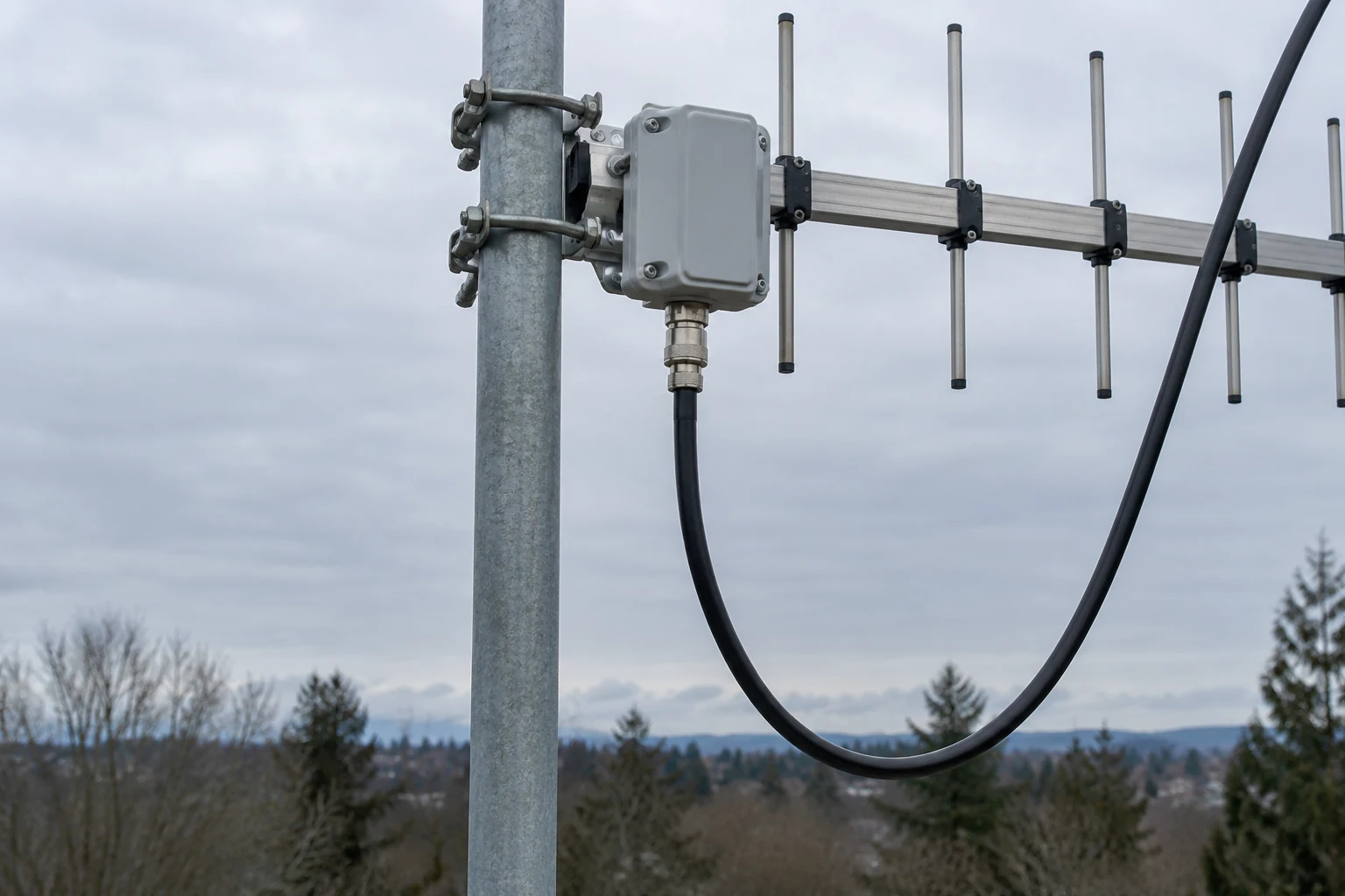
Think through the route in sections. A run might leave a protected equipment area, pass through a wall, and end at an exposed antenna connection. The exposed portion influences the cable variant, while the transition points and antenna end create separate demands on the finished assembly. Buying outdoor-rated bulk cable alone does not specify what will cover its connections. Decide where weather protection is needed when ordering the assembly, rather than discovering after installation that the cable and its termination were treated as one purchase decision.
Connector choice is similarly specific to the cable being terminated. Times lists connector parts sized for LMR-240 in its 240 datasheet and a specific 400-series N-male connector in its LMR-400 datasheet. Thus, “N-male” describes only part of the order: the cable-side connector must also be specified for the selected cable size. This matters if a portable kit uses one cable for easy handling while a fixed installation uses another; sharing an equipment-side connector style does not make their cable-side connector parts interchangeable.
Whether buying a preterminated run or ordering bulk cable and connectors separately, make the assembly details explicit before purchase. For a preterminated run, ask which cable variant and cable-sized connectors are supplied, and whether weather-protection parts are included. For a separately assembled run, list those parts alongside the cable. In either case, check the proposed seal against the actual cable and connector combination rather than assuming that a part described as weatherproof fits every termination.
Plan protection for the termination as its own assembly component. The LMR-240 datasheet lists a specific weatherproof/strain-relief kit, and Times says its LMR-240 cold-shrink boot can make a weather-tight seal around an N-male connector. Those are options tied to a stated cable and connector arrangement, not evidence that any boot will seal any joint. For an exposed antenna-end connection, the useful purchase description is therefore more precise than “outdoor coax”: it identifies the selected cable variant, its cable-sized termination, and the intended weather-sealing and strain-relief parts. That extra specificity may mean ordering more components, but it keeps the exposed connection from being an afterthought.
Account for Antenna Mismatch Before Trusting the Loss Estimate
A low standing-wave ratio (SWR) at the transceiver does not necessarily mean the coax is carrying a well-matched signal. If a tuner sits in the shack, it can present a suitable match to the radio while high SWR remains along the cable between the tuner and antenna . The radio-side reading tells you what the radio sees; it does not, by itself, settle what is happening on the long run.
That distinction matters when comparing cables by their published matched-loss figures. With elevated SWR in the tuner-to-antenna coax, some power can be wasted as heat, so the operating loss may be more consequential than the matched-loss figure suggests . ARRL specifically warns that coax loss under high SWR can become serious on the higher HF bands . A cable that looks acceptable by its nominal loss alone may therefore be a poor answer to a persistent antenna mismatch.
Consider a station that tunes successfully from the operating desk but uses a long coax run to an antenna that is not well matched on the chosen band. Swapping in lower-loss cable may help, but it does not remove the high SWR on that run if the matching arrangement stays the same. One alternative is to put a remote tuner near the antenna: ARRL says this can keep the long coax run close to a 1:1 SWR . In that arrangement, the long run and the antenna-side connection no longer have the same matching problem as a shack-tuner installation.
The tradeoff is an installation decision, not just a cable specification. A tuner near the antenna changes where matching occurs, while a cable change addresses the cable itself. If the concern is chiefly high SWR along a long run, reconsidering tuner placement may be more useful than treating a thicker cable as the only remedy. If the antenna is already well matched, that particular reason to move the tuner is less compelling. Keep the tuner’s location and the SWR on the coax in view when interpreting any loss estimate; a reassuring match at the radio is not proof of a low-SWR feed line .
Make a Conditional Choice and Verify It Before Buying
A compact cable can be a reasonable choice when the run is short and the antenna’s standing-wave ratio (SWR) is low: ARRL considers RG-58 acceptable in that mobile situation . That is a conditional judgment, not a reason to choose it by name alone. If the cable has to make tight turns or move with the installation, its physical fit may matter as much as the loss figure. If the route is exposed, the decision also includes the jacket, connectors, strain relief and weather protection—not just the cable sold by the foot.
The decision changes for a long UHF feed line. ARRL warns against RG-58 for a 100-foot run near 440 MHz . Rather than extend the short-mobile-run judgment to that installation, compare loss at the intended frequency and full installed length. A lower-loss cable may be worth its added bulk if the route accommodates it; a physically convenient cable is less attractive if the calculated loss defeats the purpose of the run. Treat antenna SWR as part of that decision, since a matched-loss figure alone does not describe every operating condition.
Before ordering, write down the specification for the complete assembly: 50-ohm cable and compatible connectors; loss for the actual band and length; a power rating applicable to the intended operating conditions; a workable route for its bends, movement and weight; and protection for any outdoor exposure. Include the antenna SWR you expect, rather than assuming a tuner at the radio resolves what happens along the feed line. If one of those inputs is unknown, the useful next step is to resolve that input—not to declare a cable the universal winner.
Continue reading
Keep learning about radio