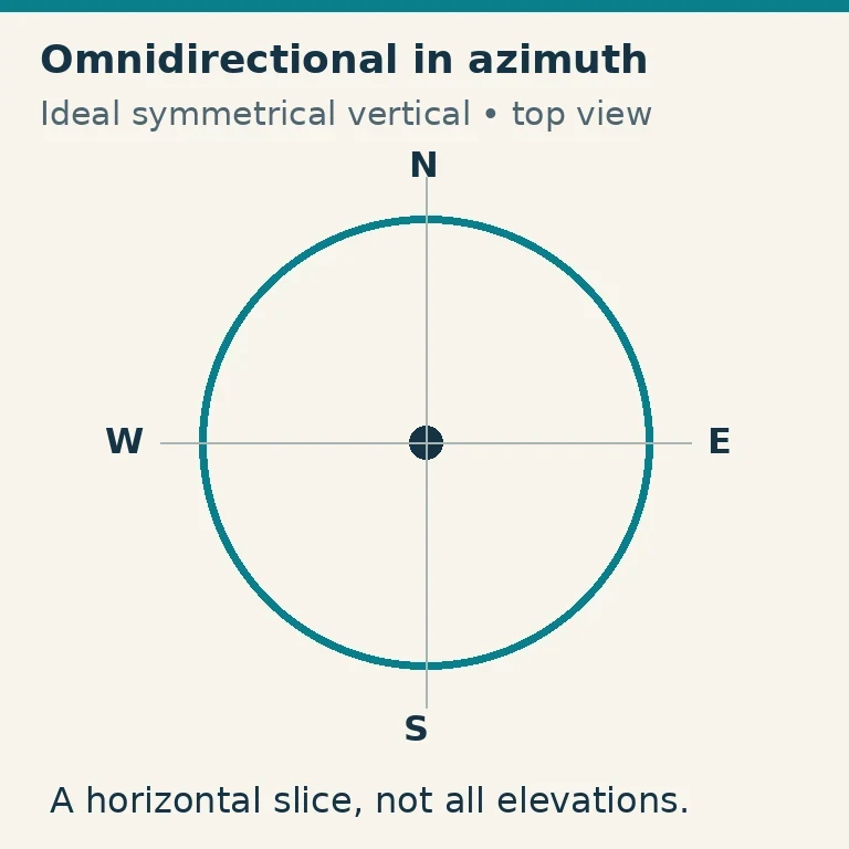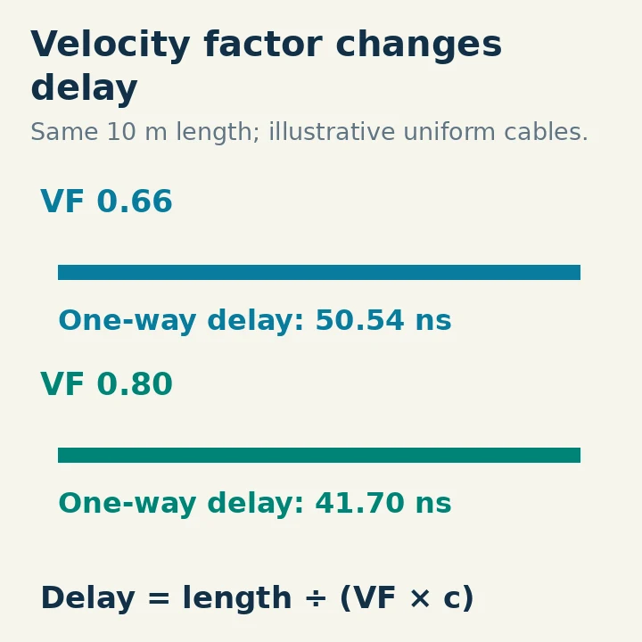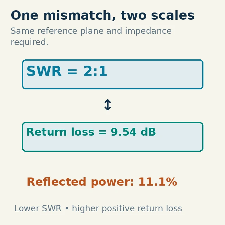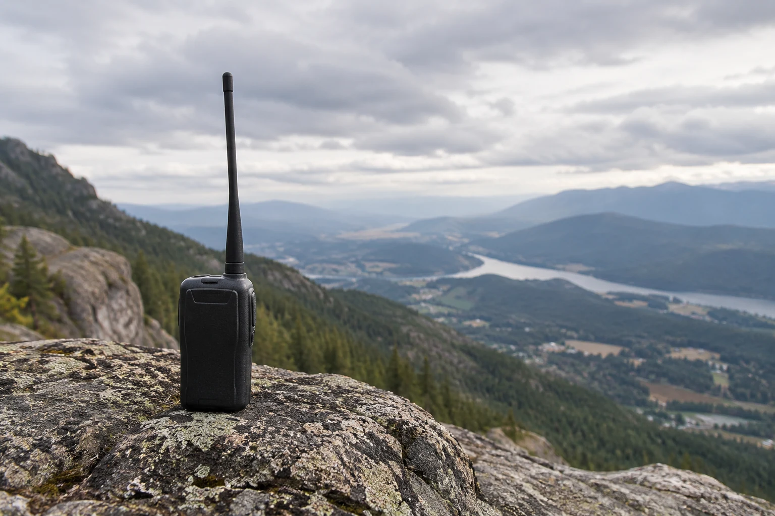
Raising a VHF antenna can extend a local communication path by giving the signal a better route over Earth’s curvature and past obstructions. Height helps at either end of the path: moving a handheld to higher ground can matter, and so can raising the antenna at the station it is trying to reach. But height is not a range setting. A calculated radio horizon describes an idealized limit, while a real contact also depends on hills, buildings, the other station’s position and the losses in the antenna installation. The useful question is not simply how high can the antenna go? It is what changes along this particular path?
Why Raising an Antenna Changes the VHF Path
For ordinary local terrestrial VHF communication, start with a mostly direct-wave mental model. The signal travels between stations along a path that can be affected by what lies between them. The ARRL describes direct waves as chiefly associated with VHF, UHF and microwave frequencies, and defines the radio horizon as the distance at which Earth’s curvature effectively blocks a signal between two points. Raising an antenna increases the distance to that curvature-limited horizon.
Picture two antennas facing across otherwise unobstructed ground. Each has its own horizon. A low antenna can see only so far before Earth’s surface curves into the path; a higher antenna can see farther. For a two-station estimate, the contribution from one end can be added to the contribution from the other. That is why the height of the distant station matters as well as the height of the station you control. The ARRL-hosted handbook uses this two-end approach in an example with an automobile antenna and a tower-mounted antenna.
This is a way to understand a potential path, not a claim that the signal stops at a sharp boundary. The same handbook says ordinary atmospheric refraction typically bends radio waves enough to place the radio horizon somewhat beyond the purely geometrical horizon; it also says the effect depends on local weather. Its approximate horizon rule incorporates that ordinary bending rather than describing a perfectly straight ray through an unchanging atmosphere.
Nor does an occasional long contact overturn the local-path model. The ARRL notes that tropospheric bending can permit contacts beyond the visible horizon. It also describes ducting under a temperature inversion, when radio waves can travel unusually long distances before returning to Earth. Those are conditional propagation possibilities, not distances to assume for routine local VHF coverage.
The horizon therefore answers one narrow question: How far might the curvature-limited reach extend from these antenna heights under the approximation’s assumptions? It does not answer whether a ridge crosses the route, whether one antenna sits in a poor location relative to surrounding ground, or whether enough signal reaches both radios. Keeping those questions separate makes a height calculation useful rather than misleading.
Estimate the Change in Radio Horizon
An ARRL-hosted technical handbook gives this approximate rule for one end of a path:
One-end radio horizon in miles ≈ 1.41 × √(antenna height in feet)
Use feet for the antenna height and read the result in miles. The multiplier reflects the handbook’s allowance for ordinary atmospheric refraction. Treat the result as an idealized, unobstructed-path estimate: the handbook warns that atmospheric effects depend on weather and that its two-station calculation does not work well as a description of hilly or rolling terrain. It is not a predicted contact distance.
To estimate a two-station curvature-limited path, calculate each antenna’s one-end horizon and add the results. The handbook does exactly that in its automobile-to-base-station example. The addition is transparent geometry: each endpoint contributes a distance to its own horizon. It does not establish that the stations have a clear path or can exchange signals at the total distance.
Consider these illustrative antenna heights, chosen to show what changes when only one end is raised:
| Illustrative path | First antenna’s one-end estimate | Second antenna’s one-end estimate | Combined horizon estimate |
|---|---|---|---|
| 5-foot endpoint to 30-foot endpoint | 1.41 × √5 ≈ 3.2 miles | 1.41 × √30 ≈ 7.7 miles | 3.2 + 7.7 ≈ 10.9 miles |
| Same 5-foot endpoint to a raised, 60-foot endpoint | 1.41 × √5 ≈ 3.2 miles | 1.41 × √60 ≈ 10.9 miles | 3.2 + 10.9 ≈ 14.1 miles |
The second estimate is about 3.2 miles greater. That is the change in the estimated combined radio horizon, not an observed increase in coverage and not a promise of a contact at 14.1 miles. The heights in the comparison are illustrative; the underlying rule and the method of adding endpoints come from the ARRL-hosted handbook.
The square root explains an important feature of the result. Doubling the second antenna from 30 to 60 feet does not double its one-end horizon, much less the combined estimate. The unchanged 5-foot antenna still contributes about 3.2 miles. Conversely, changing the 5-foot end would change the total too, even if the distant antenna stayed where it was. That is useful when comparing choices: you need not assume that only the tallest tower, or only the transmitting station, controls the geometric estimate. This interpretation follows directly from the handbook’s stated formula and two-height method.
The calculation is best used as a bounded comparison between proposed positions. If a modest height increase produces a modest horizon change, a hill blocking the actual route might matter more than the new number. If the target lies near the estimated curvature limit and the route appears open, the change may be worth investigating. Either way, check the ground along the path and the complete installation before turning a horizon estimate into a siting decision.
Why the Surrounding Terrain Can Matter More Than Mast Height
“Antenna height” needs a reference point. An antenna may be 30 feet above a roof, yet the roof may sit below nearby surrounding ground. Another antenna on a shorter mast may occupy a much better-situated high site. As an explanatory comparison—not a quantified prediction—the shorter mast can have the more promising path toward a particular station if its site clears the terrain that blocks the taller mast. The ARRL describes repeaters on mountains or tall buildings as using a better radio horizon and associates such sites with height above average terrain.
Local mounting height and height relative to surrounding terrain are related, but they are not interchangeable. A dated example of why prediction models distinguish them appears in ITU-R P.370-7, from 1995. For that model, effective transmitting antenna height is measured above the average ground level from 3 to 15 km away in the direction of the receiver. Its receiving antenna height is defined above local terrain. Those are definitions within that particular propagation model—not a universal HAAT or FCC standard, and not a recommendation to use the 1995 model as a current prediction method. They illustrate how an antenna can have one height above nearby ground and a different relationship to the terrain along the intended direction.
The direction matters because a path is not an average of every direction around a station. A nearby ridge between two antennas can dominate a route even if the sites look promising by a simple horizon calculation. Hills, mountains and tall buildings can affect line-of-sight propagation, according to the ARRL. In its own prediction context, ITU-R P.370-7 also says received field strength depends on receiver height and its immediate surroundings, and that accounting for local terrain through a terrain-clearance angle can improve predictions for a receiving area. Those observations support inspecting the specific route; they do not supply a universal correction that can be added to the simple horizon formula.
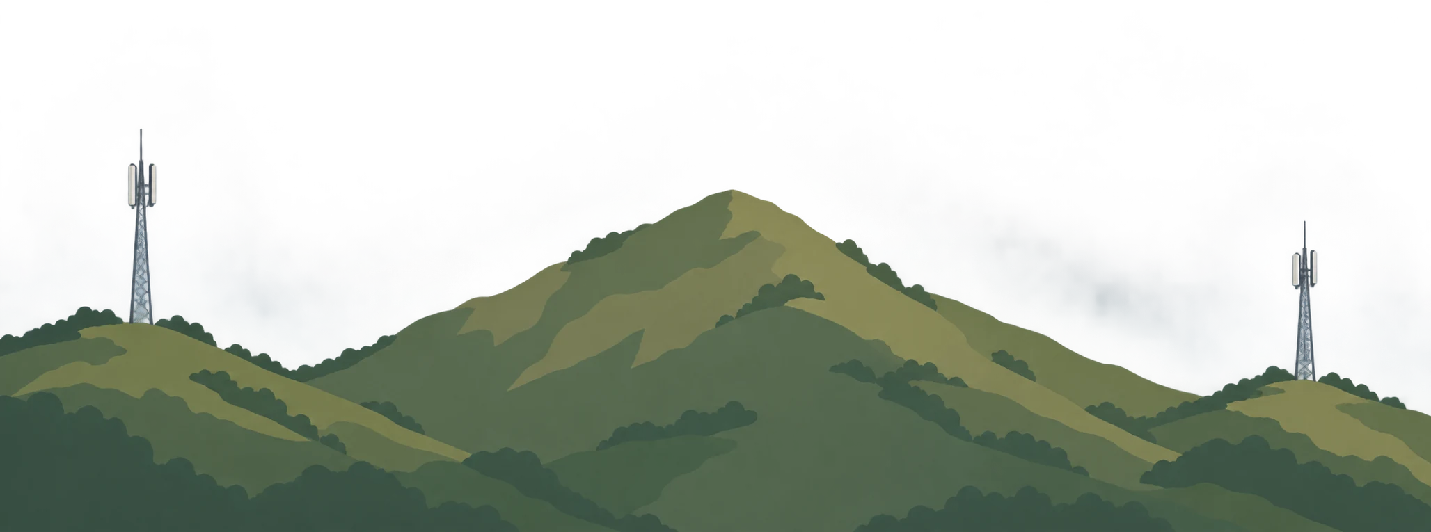
A clear-looking line between antenna tips is not the entire obstruction question, either. The first Fresnel zone describes space around a designed radio path’s direct ray that is relevant to diffraction near obstacles. The ITU radio-relay handbook explains that clearance between the ray and an obstruction can avoid diffraction loss and expresses that clearance in terms of the first Fresnel zone. For the designed paths it discusses, it treats an unobstructed first Fresnel ellipsoid as a practical condition for negligible diffraction. That is a reason not to equate a barely visible ray with an obstruction-free path. It is not a universal clearance threshold for a moving amateur handheld or every local VHF contact.
These terrain ideas lead to a practical distinction. Suppose a proposed mast extension improves the calculated horizon, but a ridge still stands in the direction of the station you want. The sensible next investigation is whether a different operating position or antenna site offers a clearer route over or around that terrain. If the site is already well placed and the path is limited mainly by curvature or a nearby obstruction the extension could clear, additional height becomes a more plausible change. These are conditional judgments about the route, not guaranteed outcomes from a map or formula.
Apply Height to Simplex, Repeater and Base-station Paths
Simplex means the two operators communicate directly on the same frequency, without a repeater between them. For a handheld simplex contact, both operators’ antenna positions matter: moving one handheld changes one end of the path, while the other station’s height and surrounding terrain remain part of the result. The ARRL specifically suggests gaining height from places such as a hill, mountain or tall building.
If a handheld starts in a low spot behind a hill, moving to a suitable high operating spot may change the terrain obstruction as well as its curvature-limited horizon. A small height change at the original spot may leave the same hill in the way. The high-spot choice is therefore more compelling when it opens the intended route; it is not a general promise that every hilltop reaches every station. The ARRL’s report of a handheld reaching 100 miles from Pikes Peak is an example from a particular high site, not a portable-radio range specification.
A repeater changes which path you are trying to complete. Repeaters commonly occupy high sites to obtain a better radio horizon. But hearing a repeater’s transmitter does not establish that your handheld signal reaches its receiver. For a successful exchange through it, you must both hear its transmission and reach its receiving side. If reception is good but you cannot be heard through the repeater, investigate the handheld-to-repeater path rather than treating the received signal alone as proof of two-way coverage.
For a fixed base station, height presents two distinct choices: raise the antenna at the present property or place it at a better-situated location, where that is an available option. Raising the home antenna changes its contribution to the two-end horizon estimate. A different site may also change the surrounding terrain and obstacles. Neither choice can be judged solely by feet above a roof. The ARRL emphasizes the importance of VHF/UHF antenna height, while its high-site advice explains why the location that supplies that height matters.
The same reasoning works in the other direction. If the distant station moves higher while the base stays put, the combined horizon estimate changes; if either end moves to a clearer site, the obstruction picture may change too. For simplex, consider the two operators’ sites. For a repeater contact, consider each required path to and from the repeater. For a base installation, compare the site and antenna arrangement with the particular stations or areas it is meant to serve. In every case, the useful question is which endpoint and which obstruction the proposed move actually changes.
Check Whether an Installation Change Improves the Whole Path
A higher antenna can require a longer feedline—the cable between radio and antenna. Feedlines lose some energy, and the ARRL says loss at a given frequency varies by feedline type. It rates loss in decibels per 100 feet, which gives a way to compare an existing run with a proposed one. Thus a mast extension may improve the outdoor path while adding cable loss; height alone does not establish the net result.
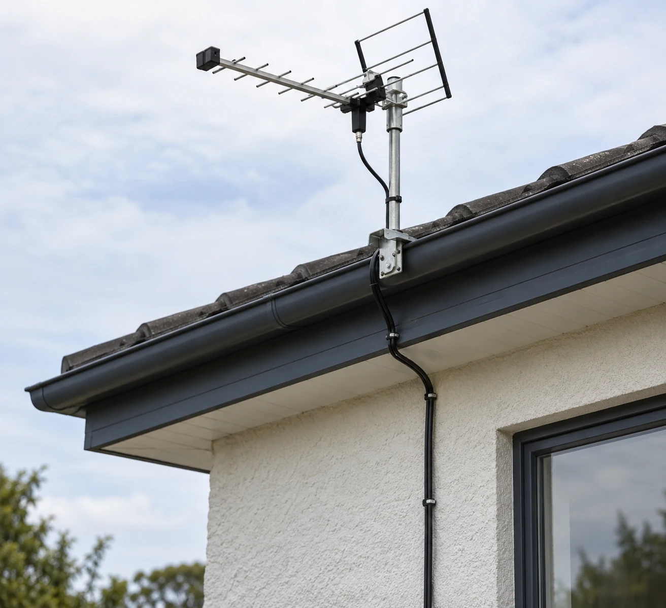
Compare the cable options at the actual VHF operating frequency and at the lengths the installations would require. ARRL’s warning about a 100-foot run of RG-58 at 440 MHz is an adjacent-frequency illustration at UHF, not a measured VHF loss figure to copy into this decision. Its general point still applies: cable choice, frequency and run length belong in the comparison. If the proposed antenna position needs much more feedline, determine whether a suitable run keeps that cost acceptable before claiming an improvement.
Antenna direction is another separate check. The ARRL notes that a directional beam focuses transmission and reception in one direction; pointing it away from a desired station can make communication difficult or impossible. If one target path performs poorly while another direction works, examine where the antenna is pointed before attributing the difference to insufficient height. Changing height will not, by itself, correct a pointing choice that favors the wrong route.
A useful comparison can stay focused on five questions:
- Where are both antennas, and which direction is the target? Mark the existing and candidate positions so the comparison concerns the same intended path.
- How much does the horizon estimate change? Calculate each endpoint separately with the approximate rule, then add them. Record the difference as an estimate, not as measured coverage.
- What lies along and near the route? Look for intervening hills, ridges or buildings and for obstructions near either station. If more precise prediction for a receiving area is needed, ITU-R P.370-7 illustrates why local terrain clearance can matter, without making its dated model a universal amateur-path method.
- What changes in the installation? Compare the present and proposed feedline types and lengths at the operating frequency, and check whether a directional antenna still favors the target.
- What happens from the candidate position? Under comparable conditions, check both reception and whether the other station can hear you. For a repeater, those are distinct parts of the required exchange. The observations test the proposed change more directly than a horizon number alone.
The resulting choice can be conditional rather than vague. Favor a higher operating spot or clearer route when a ridge or other terrain feature dominates the intended path. Consider raising the mast when the added height plausibly improves horizon or clearance on that route and the proposed feedline run does not undermine the installation. Investigate cable or direction first when the outdoor path looks promising but added loss or antenna pointing is the more apparent problem. These decisions preserve three separate checks—curvature-limited horizon, clearance along the actual path and signal delivered through the installation—rather than turning any one estimate into guaranteed VHF coverage.