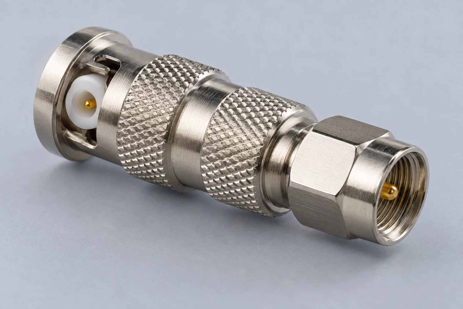
Read an antenna connector’s name as a description of one mating interface, not as a complete adapter recommendation. Before ordering, identify the connector family, plug or jack designation, and center pin or socket on both the equipment and the cable or antenna. Then specify the mating interface the adapter must provide at each end. A matching-looking shell—or a listing that says only “male to female”—does not settle whether the contacts will mate.
The adapter must also fit the application, not merely screw or latch into place. Compare the exact part’s impedance, frequency and power specifications with the requirements documented for your setup. If an interface or an essential rating remains unclear, the safer buying decision is to resolve it or choose a better-documented part.
Identify the Two Connections the Adapter Must Make
Start with the two things you already own. Find the equipment manufacturer’s designation for its antenna port, then find the documentation for the existing feed line or handheld antenna connector. Record those descriptions separately. If a cable was assembled or modified after purchase, its original paperwork may no longer describe the end in front of you; inspect that actual end rather than relying on the cable’s name.
Break each description into three questions:
- What is the connector family? Names such as SMA and BNC identify different interface families. Do not treat a similar-looking outside diameter as a family designation.
- Is the exposed interface called a plug or a jack? Record the word used in the port or cable documentation. Also note whether it is on a loose cable or antenna, or fixed to an equipment panel. Those are descriptions of where the interface is mounted, not substitutes for its mating designation.
- What is at the center? Look for a pin or a socket, and verify it against the exact interface documentation when available. Do not fill this field in from “male” or “female” alone: reverse-polarity versions make the center contact an especially important separate check.
The object is to describe what the adapter will face, not yet to copy a product listing. A useful worksheet might read: “equipment port: documented family ___, documented jack/plug ___, inspected center ___”; then “existing cable or antenna: documented family ___, documented jack/plug ___, inspected center ___.” If a port is recessed, use the equipment documentation and a clear view of the interface rather than guessing at a partly hidden contact.
Now write a second line for each side: “adapter end needed to mate with this interface: family ___, plug/jack ___, center pin/socket ___.” An adapter has two separate ends, and each needs its own answer. The end that meets the radio need not have the same family as the end that meets the feed line; that is often the reason to buy an adapter at all. Conversely, finding a product with the right name on one end says nothing yet about its other end.
This is a purchasing check, not an invitation to try combinations until one fits. Amphenol RF’s SMA selection guidance includes connector gender alongside cable type, frequency range, mounting configuration and environmental requirements. That is a useful reminder that a short product title is only part of a selection, even when the family name is correct.
Resolve Standard and Reverse-polarity Look-alikes
The distinction between SMA and RP-SMA shows why the center-contact line matters. Amphenol RF describes SMA as a 50-ohm threaded coaxial RF interface. It describes RP-SMA as retaining the threaded interface while reversing the gender of the center pin. Thus, recognizing familiar SMA-style threads does not, by itself, establish the center-contact arrangement of a proposed purchase.
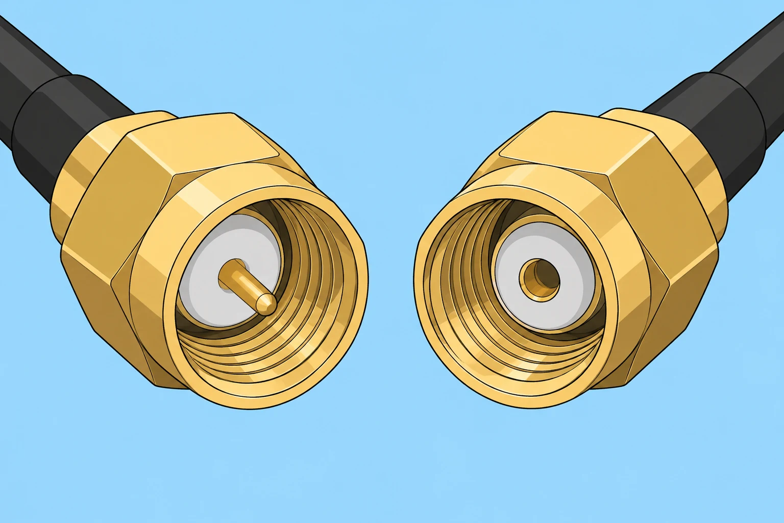
Suppose your port documentation calls its interface RP-SMA. Do not shorten that to “SMA” when searching, even if a candidate adapter appears to have the right threaded shell. Record the port’s documented plug or jack designation and inspect its center contact. For the candidate adapter, confirm the mating plug or jack designation and the complementary center contact in its actual drawing. If the proposed contacts are both pins or both sockets, the apparent shell match has not solved the connection. If you cannot establish the contact arrangement from the documentation and inspection, pause rather than ordering on the basis of the threads.
“Reverse polarity” is a connector-contact designation here; it is not a statement about the positive and negative leads of a DC power connection. Nor is RP a standalone connector family. Amphenol RF describes RP-BNC as using a bayonet-style connection like standard BNC, but with reversed center-pin polarity. That differs from the threaded SMA interface described on its SMA page. RP-SMA and RP-BNC therefore should not be treated as interchangeable merely because both names contain “RP.”
The practical reading order is family, mating designation, center contact. For example, a listing that gives “RP” and “male” but omits a clear family or contact drawing leaves important questions unanswered. A listing with the right family but no way to verify the center contact can be just as uncertain. Resolve the complete interface before considering price, length or convenience.
Match the Electrical and Application Requirements
A correct physical interface is necessary, but it is not the whole purchasing decision. First identify the requirements of the equipment and connection you intend to use; then compare them with the specifications for the exact adapter part. In particular, check the documented impedance requirement—such as 50 or 75 ohms where relevant to your system—along with the operating-frequency range and an actual RF power rating suitable for the intended application. Do not assign a universal power rating to an adapter from its connector family name.
Keep the scope of a family description clear. Amphenol RF describes SMA connectors as 50-ohm threaded connectors; that statement does not supply the frequency range, power rating or installation details of every individual adapter offered for sale. Its selection guidance calls out cable type, gender, frequency range, mounting configuration and environmental requirements. Use those as questions for the particular connection, not as values you can infer from the letters “SMA.”
For a cable-mounted connection, check whether the proposed part’s form fits the cable or mating connector you actually have. For a connection close to an equipment panel, consider its mounting position and the space the adapter body will occupy. If the assembly will be exposed to weather, look for an environmental provision documented for the complete connection you plan to make. A bare connector-family name is not a weather-sealing specification.
The material tradeoff is between a readily available part with an attractive-looking name and a part whose relevant specifications you can verify. If the interface is confirmed but an essential impedance, frequency, power or environmental requirement is missing or unsuitable, do not assume the name makes the part adequate. Obtain the individual specification or select a documented alternative. If both interfaces and the application ratings check out, the part becomes a reasonable purchase candidate—subject to its physical installation details.
Write the Purchase Specification and Check the Actual Part
A two-ended specification makes omissions visible. Here is an illustrative, hypothetical case, not a claim about any particular radio, cable or adapter:
- Equipment side: The radio’s own documentation identifies its port as a standard SMA jack. Inspection of this example port confirms a center socket. Specify an adapter end documented as a standard SMA plug with a center pin, subject to confirmation in the proposed part’s drawing.
- Feed-line side: The existing line’s documentation identifies its end as an RP-BNC plug. Inspection of this example end confirms a center socket. Specify an adapter end documented as an RP-BNC jack with the complementary center pin. Verify the proposed part’s plug/jack and contact arrangement in its drawing rather than deriving it from “RP” alone.
- Application requirements: Add the impedance required by the documented setup, the operating-frequency range, the RF power requirement, and any mounting or environmental conditions. Leave no required field as an assumed family-wide value.
The example’s value is its method: each adapter end is specified against the exposed interface it must meet. It does not establish that a seller’s “SMA to RP-BNC” product has those exact ends or contacts. That title could omit the details needed to decide. Compare your completed specification with the seller’s exact part number, drawing or datasheet, not a photograph of a similar item. Amphenol RF explicitly advises checking the individual product drawing or datasheet before installation.
Use that drawing to confirm both interface designations and center contacts. Then check whether the body will clear the radio housing, nearby controls or other connectors when fully assembled. Consider whether the attached cable will place strain on the connection in its intended position, and whether the part’s mounting or cable arrangement is appropriate. Read the installation instructions for that specific part: do not force an interface that resists mating or assume one SMA mating torque applies to every construction or material. No torque value or dimension can be determined from the family name alone.
The buying verdict should now be straightforward. Buy when documentation and inspection establish both mating interfaces, and the exact part’s relevant ratings and installation details meet your requirements. Pause if the threads or bayonet appear right but the plug/jack designation or center contacts remain unconfirmed. Choose a documented alternative if an essential electrical, clearance or environmental requirement is absent or unsuitable.
A correctly specified adapter joins the two identified interfaces. It does not tune the antenna, alter anyone’s operating privileges, or automatically weather-seal the finished connection.