Set an SSB receive filter wide enough to preserve understandable speech, then narrow or shift it only as much as needed to reduce unwanted sound. Start by tuning the voice correctly in USB or LSB. A narrow filter cannot fix the wrong sideband or a badly mistuned signal.
For a practical starting point, try about 2.4 kHz if your radio offers it, compare that with a wider setting, then adjust while listening to actual words. On the original IC-7300, 3.0, 2.4 and 1.8 kHz are the documented default SSB filter presets. They are convenient comparison points, not universal settings for every voice or receiver.
Know Which Bandwidth You Are Changing
Single sideband, or SSB, carries voice in one sideband of a radio-frequency signal. USB means upper sideband; LSB means lower sideband. The receive filter selects the portion admitted to the receiver's demodulation and audio path. Its width affects what reaches your ears, including wanted speech and nearby interference.
This guide concerns receive bandwidth. Microphone equalization, speech compression and transmit-bandwidth settings affect what your transmitter sends; they do not solve the same task. The IC-7300 manual documents receive IF filters and transmit filter width in separate sections. Check the control label before turning a setting that merely includes the word “filter.”
Also separate the receive filter from the spectrum span. The span is how much of the band appears on the screen. Narrowing the span may make a signal easier to inspect while leaving the audio unchanged. Look for the receive passband indicator to see what the filter actually admits.
For a receive-only adjustment session, keep push-to-talk released and VOX, voice-operated transmission, off. You can listen and compare without putting a test signal on the air.
Understand Low Cut, High Cut and Width
Some radios offer a single bandwidth number. Others let you set the low and high audio-frequency edges separately. If the passband runs from 300 Hz to 2,700 Hz, its width is 2,700 − 300 = 2,400 Hz, or 2.4 kHz. “High cut 2700” and “bandwidth 2700” are not interchangeable descriptions.
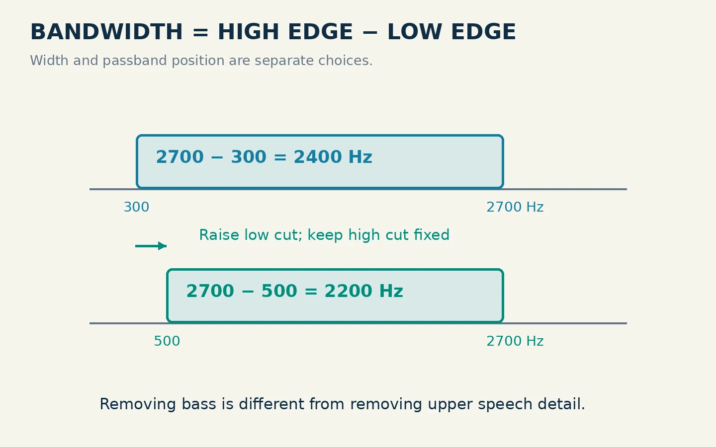
The edge drawing shows this arithmetic and a second passband from 500 to 2,700 Hz. Raising the low edge removes some low-frequency content while preserving the upper edge; its width becomes 2.2 kHz. Moving the high edge down instead removes upper-frequency content. These are teaching examples, not factory values for a particular model.
A shift moves the passband's position. A width adjustment changes the separation of its edges. If a receiver uses two passband-tuning controls, moving them together can shift the passband, while moving them relative to one another can narrow it. On the IC-7300, Twin PBT provides this behavior, and the manual warns that excessive narrowing can make the received audio disappear.
Do not judge a setting from the number alone. Two filters with the same nominal width can sit differently relative to the recovered speech. If a remembered “2.4 kHz” setting sounds wrong, check whether a shift or passband-tuning adjustment remains active.
Establish a Voice You Can Compare
Choose a station that is strong and steady enough to follow through several sentences. Use the correct sideband and fine-tune until the voice sounds natural. If it remains thin, reversed-sounding or unintelligible over a range of tuning, verify the mode before narrowing the filter further.
Restore passband shift to its normal position. Select the ordinary SSB preset rather than a narrow data-mode filter. Turn off optional noise reduction or notch filtering briefly if you can do so without losing the signal, so you can hear what the bandwidth change itself does. Keep the speaker or headphones at a comfortable level.
Begin around 2.4 kHz and listen for consonants, call-sign letters and numbers. Then compare a wider preset. The wider option may sound fuller, but it can also admit more adjacent activity or noise. The useful question is whether you understand the message more reliably, not which setting sounds richest during a quiet pause.
Use several phrases for each comparison. A voice fading at the same moment you change a filter can mislead you. If necessary, alternate between the two settings more than once while leaving frequency and other controls alone.
Reduce the Interference You Actually Have
If a neighboring signal enters from one side of the passband, try moving the affected edge inward or shifting the passband away from that intrusion. Make small changes and listen again. Watch the passband graphic, especially when changing between USB and LSB: the RF direction and the audio-frequency edge are not the same thing in both modes.
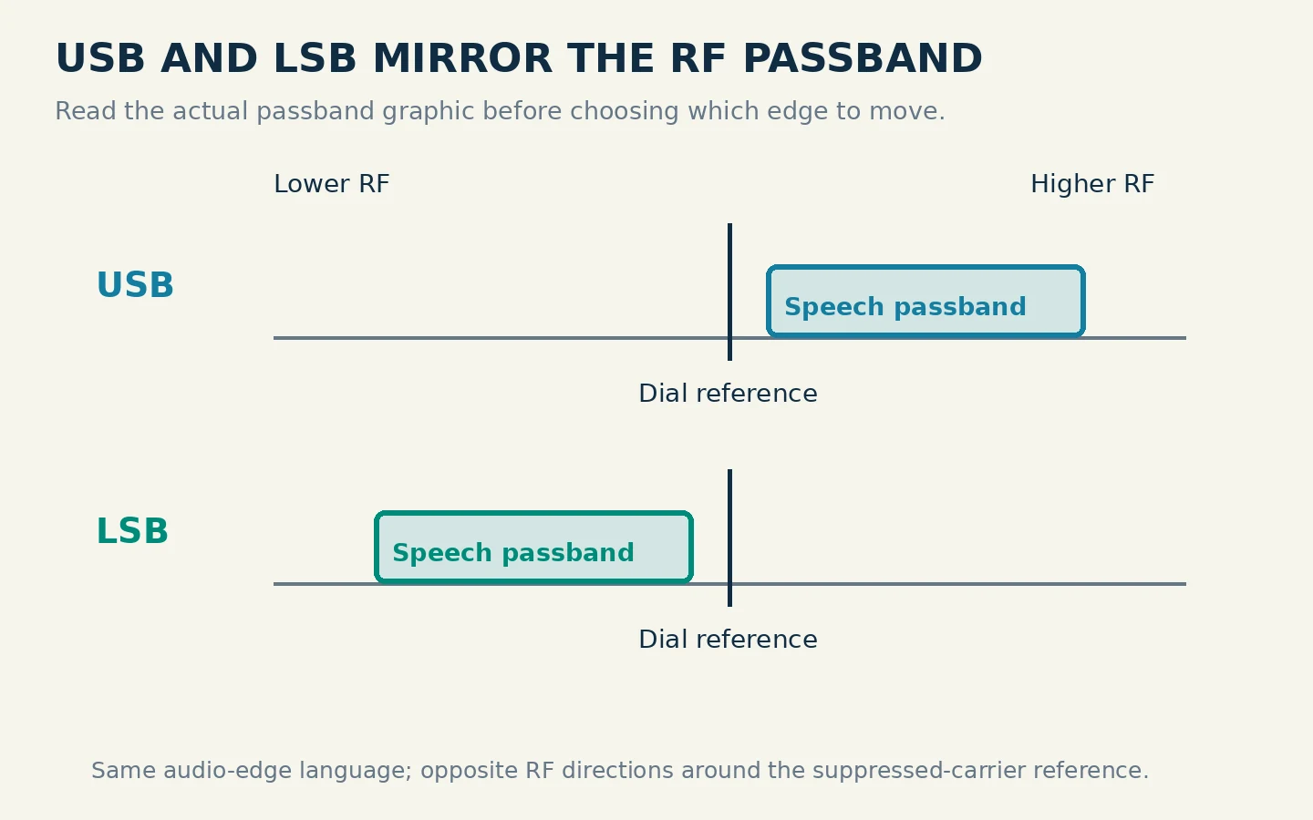
In USB, higher recovered audio frequencies correspond to RF farther above the dial reference. In LSB, they correspond to RF farther below it. Thus an interferer on the higher-frequency RF side is not always something to remove with the same audio-edge adjustment. The diagram makes that mirror relationship visible; the radio's own passband display should confirm the change.
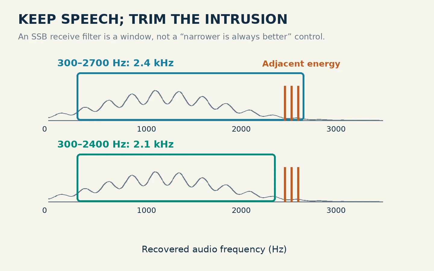
For example, imagine a USB voice with unwanted energy at the high-audio end. Lowering the high cut from 2,700 to 2,400 Hz leaves a 300–2,400 Hz passband, 2.1 kHz wide. Listen for whether the unwanted sound decreases and whether speech remains clear. If important consonants become harder to distinguish, move back toward the previous setting.
When interference overlaps the same frequencies as the wanted voice, a filter cannot separate the two perfectly. Narrower is not automatically better. A very tight passband may make the interference less annoying while making the call sign less readable. Return to the last intelligible setting rather than continuing to narrow as a matter of principle.
Use the Original IC-7300 Filter Controls
On the original IC-7300, select USB or LSB, then touch the filter icon for one second to open the FILTER screen. Touch the filter icon again as needed to choose FIL1, FIL2 or FIL3. Touch BW, rotate the main dial to adjust width, touch BW again to leave the adjustment, then press EXIT.
The manual notes that changing bandwidth resets Twin PBT to the center position. That matters when comparing settings: you may be changing both width and a previously shifted passband at once. Check the graphic rather than assuming a previous PBT adjustment survived.
To clear Twin PBT independently, hold TWIN PBT CLR for one second. The manual describes a dot by the bandwidth indication when PBT has been adjusted; clearing the setting removes the dot. This gives you a useful way back after an experiment makes speech disappear.
The names and gestures above belong to that model's manual. On another radio, look for receive filter, IF width, low/high cut, shift or passband tuning in the matching documentation. Do not copy the IC-7300's touch sequence onto a similar-looking radio.
Recognize Problems Bandwidth Will Not Solve
| What you hear | Check before narrowing more |
|---|---|
| A steady whistle within the voice | A manual notch may target a narrow tone more selectively; preserve the voice while adjusting it |
| Chopped or watery speech | Reduce optional noise reduction and compare again |
| Strange speech pitch on the whole signal | Fine tuning and the USB/LSB selection |
| Many unwanted signals or an overflow indication | Receiver gain, preamplifier and attenuation settings under the manual's overload guidance |
| Little or no audio after several adjustments | Reset shift/PBT, widen the filter and verify the mode |
The IC-7300 provides distinct notch, noise reduction and gain controls; they have separate purposes from IF bandwidth. Try one correction at a time so you know which change helped. If another transmitter is genuinely distorting or splattering into your passband, receive filtering may reduce the annoyance but cannot repair that transmission.
Keep a normal preset you can return to, and note any useful low/high edges or width-and-shift combination. Include the mode and interference condition in that note. A setting that helps one crowded contact may unnecessarily dull a later clear signal. Reopen the filter when conditions allow and let intelligibility determine the final setting.