Microphone impedance describes the electrical behavior of a microphone's output or a radio's microphone input. It matters because the microphone must deliver an appropriate audio signal into the radio's load. However, a matching ohm number alone does not establish compatibility: output level, microphone power, balanced or unbalanced wiring, connector pinout and push-to-talk all matter too.
Start with the exact microphone and radio documentation. A connector that fits—or an adapter advertised for the same plug shape—does not prove that the audio or supply pins are connected correctly.
Distinguish Source Impedance from Input Impedance
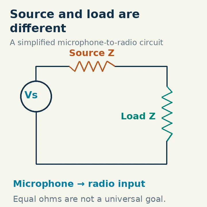
The microphone is the source of the audio voltage. The radio's microphone input is the load receiving it. Both may be described with an impedance value in ohms, but those values refer to opposite sides of the connection.
In many modern audio circuits, a relatively low source impedance drives a higher load impedance. This is often called voltage bridging. Rane's audio application note explains that modern solid-state audio stages generally aim to transfer voltage rather than maximize power by making source and load impedances equal.
That does not mean every radio input follows one universal ratio or that every specification labeled “microphone impedance” is a precise measurement of the preamplifier's load. Some manuals state the intended microphone impedance; others describe the connector input. Preserve the manufacturer's wording and use its compatibility guidance instead of guessing from the number alone.
The original IC-7300 manual labels its microphone-input pin with an impedance of 600 ohms. That is useful information for that radio, but it is not a rule that all microphones used in amateur radio must measure 600 ohms. Other equipment can be designed for different microphone systems.
Use a Voltage-divider Example to Understand Loading
A simplified model treats the microphone as an ideal voltage source followed by a source resistance, feeding the radio's input resistance. For this teaching example, ignore frequency-dependent reactance and write:
Input voltage = source voltage × load resistance ÷ (source resistance + load resistance).
Suppose a 200-ohm source drives a 2,000-ohm input. The input receives about 2,000/2,200, or 91%, of the source's open-circuit voltage. If the same 200-ohm source drives a 200-ohm input, the input receives half that voltage. The second arrangement is an equal-impedance connection, but it does not preserve as much audio voltage.
Rane demonstrates this same loading principle using audio circuit examples. Its central point is that deliberate equal-impedance matching can introduce loss where voltage transfer was the objective.
Real microphones and inputs need not behave as pure resistors across the entire audio band. Loading can therefore affect response as well as level. The example explains the principle; it is not a design calculation for an unspecified microphone adapter.
Also avoid confusing microphone impedance with a DC resistance reading. A multimeter reading across a coil is not a complete AC impedance specification, and measuring a powered element as though it were a passive resistor may tell you very little about how it should connect.
Impedance Is Not Sensitivity
Microphone sensitivity describes the electrical output produced for a stated acoustic input. Two microphones with similar impedance can deliver very different signal levels when you speak at the same distance. A radio can therefore sound weak with a microphone that is electrically safe but insufficiently sensitive for the available gain.
Conversely, an amplified microphone or external audio processor can overload the input even though its source impedance is acceptable. Turning up the radio's microphone gain is not a universal cure for an adapter that delivers the wrong kind of signal.
Keep microphone-level audio separate from line-level or speaker-level output. A computer or mixer output may need an appropriately designed interface, attenuation and isolation before feeding a radio microphone input. A plug adapter does not perform those functions merely by rearranging contacts.
For a practical comparison, begin with the manufacturer's supplied microphone and ordinary settings if it is available. Establish that the radio itself produces clean audio before adding an external microphone, preamplifier and cable. Change one element at a time so you can locate the cause if the sound deteriorates.
Check Dynamic, Electret and Powered Microphones Separately
A passive dynamic microphone generates audio without requiring a power supply for the microphone element itself. An electret system commonly needs bias or a powered circuit. A condenser microphone that expects professional phantom power is a different arrangement again. Do not treat all three as interchangeable because each is called a microphone.
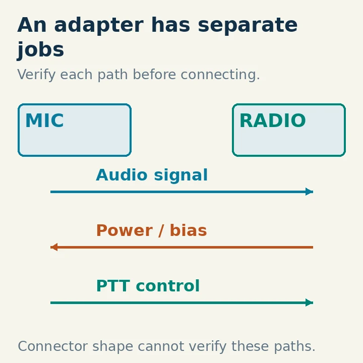
The original IC-7300 microphone connector includes a separate +8 V output, microphone input, grounds and PTT-related contacts. That pinout demonstrates why supply and audio functions must be checked individually. It does not authorize feeding arbitrary external power into the radio.
Never connect a professional phantom-power supply to a radio input unless a documented interface explicitly provides the required separation and compatibility. Likewise, do not assume a radio's accessory-voltage pin supplies the correct bias through the correct path for a computer headset.
A bias-blocking capacitor, transformer, resistor network or active preamplifier may form part of a suitable interface. The required circuit depends on both devices. If the manufacturer does not provide an approved adapter or complete wiring diagram, seek qualified help rather than constructing a cable by trial and error.
Balanced Wiring Is Another Independent Question
A balanced audio connection uses two signal conductors with an impedance relationship intended to reject common-mode interference at a suitable input. It is not simply a synonym for “low impedance,” and it is not guaranteed by the use of an XLR connector alone.
A radio microphone input may be unbalanced. Connecting a balanced microphone or processor to it can require a specified transformer or wiring arrangement. Rane's application note explains that balanced and unbalanced output stages can behave differently when one side is grounded, including level changes and problems for some active output circuits.
For that reason, “tie the spare wire to ground” is not a safe general instruction. Follow the source device's unbalanced-connection instructions and the radio's input diagram together. Verify the connector-view orientation: a drawing of a socket viewed from the front can be mirrored relative to the solder side of a mating plug.
PTT, or push-to-talk, also needs its own correct switching path. A microphone can produce excellent receive-monitored audio while its PTT wiring is wrong, or key the radio correctly while its audio wiring is wrong. Test the two functions separately.
Build a Compatibility Sheet Before Connecting
For the radio, record the microphone-input specification, required audio level if supplied, connector pinout, permitted supply output and PTT switching requirements. For the microphone, record element type, source impedance, sensitivity, power needs, output wiring and connector assignments.
Compare the two records. If you need an adapter, identify what it must do: change connector wiring, block bias, supply the microphone appropriately, change level, provide balanced/unbalanced conversion, or combine several of those tasks. “Impedance adapter” is too vague to approve the connection.
For a headset, verify the earphone path independently. Its impedance and wiring concern a receive-audio output, not the microphone preamplifier. A headset can satisfy one side while failing the other.
Keep the original microphone or a known working configuration available. Retain the adapter's actual schematic and label it with the supported radio and microphone, rather than just the connector type. That reduces the chance that a working cable will later be used with an incompatible radio.
Commission Audio Without Hiding the Fault
With the station in a known state, reduce audio gain settings, disable unnecessary speech processing and verify the approved wiring before applying power. Test receive monitoring or a properly arranged recording path if the radio provides one. Monitoring is useful for gross faults, but it is not a calibrated proof of your transmitted spectrum.
For a transmit test, use an appropriate load and the manufacturer's permitted setup procedure, or arrange a short authorized on-air report. In US operation, the control operator's license must authorize the frequency and mode, and the transmitted emission must fit the permitted segment. Checked against FCC Part 97 on October 29, 2026.
Increase microphone gain only enough for normal speech, following the radio's ALC or other audio-level guidance. Here ALC means automatic level control; use the operating region documented for the model rather than an arbitrary meter reading. Ask for clarity and distortion reports rather than merely “is it loud?” If gain must be extreme, pause to check sensitivity, loading and the adapter instead of masking the problem with compression.
If you hear hum or RF-related distortion, investigate cable shielding, wiring and common-mode paths; do not diagnose every noise as an impedance mismatch. If PTT operates unexpectedly, stop and recheck the pin assignments. A compatible microphone connection is one in which level, loading, power, wiring and control all agree—not one in which a single number happens to match.