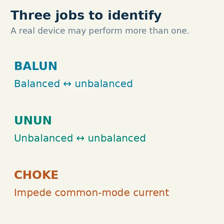
A balun handles a transition between balanced and unbalanced systems. An unun handles an unbalanced-to-unbalanced transformation. A common-mode choke impedes unwanted current flowing in a common-mode path, such as along the outside of a coax shield. These names describe related but different jobs, and one device can perform more than one job.
Start with the required function, then check the transformation ratio, circuit design, frequency range, load conditions and power rating. A “4:1” label alone does not tell you whether a device provides useful common-mode isolation. A “1:1” label does not mean it does nothing.
Separate Balance, Impedance and Common-mode Current
Three questions usually explain the confusion:
- Does the connection cross between balanced and unbalanced systems?
- Must the differential-mode load impedance be transformed?
- Must an unwanted common-mode current path be impeded?
Balance concerns how a circuit relates to its surroundings, not simply whether it has two wires. A symmetrical dipole and parallel-wire feeder are commonly treated as balanced structures. Coax is an unbalanced transmission line: its shield provides a reference and separates the internal transmission-line fields from the surrounding environment. The installed antenna, nearby metal and feed-line routing can disturb an otherwise symmetrical arrangement.
Impedance describes voltage and current at a specified frequency and reference point. An antenna can be balanced yet present an inconvenient impedance to a 50-ohm radio. It can also present a reasonable impedance while allowing unwanted feed-line current. Matching and common-mode control therefore require separate evidence.
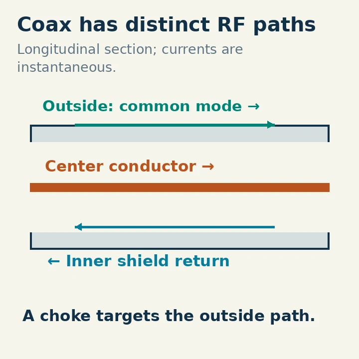
Common-mode current on coax is associated with the outside surface of the shield at RF. It can make the feed line participate in radiation or noise pickup and create additional coupling into station equipment. Whether it causes a practical problem depends on the antenna and installation. It is not sensible to conclude that every noise problem or RF symptom has the same cause.
What a Balun Actually Does
“Balun” abbreviates balanced to unbalanced. A familiar application is feeding a balanced dipole from coax. The device must be appropriate for the impedance and common-mode conditions at that feed point. The descriptive name does not specify its ratio or guarantee its performance.
A 1:1 current balun is often implemented as a common-mode choke on the feed line. It aims to impede the unwanted common-mode path while leaving the intended differential transmission substantially unaffected. Because its impedance ratio is nominally 1:1, it is not intended to turn an arbitrary antenna impedance into 50 ohms.
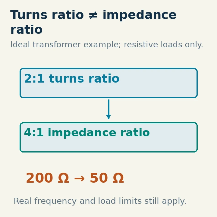
A 4:1 balun adds an impedance-transformation function. Under the intended ideal conditions, it can transform a 200-ohm differential load toward 50 ohms in the appropriate connection direction. That does not mean every antenna described as a “200-ohm antenna” stays at 200 ohms on every band, or that a real device remains lossless under any load. Frequency-dependent resistance and reactance still matter.
The terms current balun and voltage balun describe different circuit behavior. A current design seeks to control the common-mode path and support the desired differential currents. A voltage design seeks a specified voltage relationship. Those objectives can behave differently with an asymmetric load. Do not assume that a voltage-balun label establishes the common-mode choking performance needed in your installation. Circuit topology and measurements are more informative than a broad product name.
What an Unun Changes
“Unun” means unbalanced to unbalanced. A typical application transforms between coax and an unbalanced antenna feed arrangement. Examples encountered in amateur stations include impedance transformers for certain end-fed antennas and matching arrangements for other unbalanced loads.
The ratio must correspond to the intended antenna system. A 9:1 transformer is not a universal random-wire tuner, and a high-ratio transformer used with a resonant end-fed antenna is not interchangeable with every other end-fed matching device. The antenna length, frequency, return path and tuning arrangement change the load seen by the transformer.
An unun can transform differential impedance without providing the common-mode isolation needed on the feeder. Consequently, an antenna installation may legitimately contain both an impedance-transforming unun and a separate choke. They are not automatically redundant. Their locations and functions need to be explained by the antenna design rather than selected by the number of ferrite boxes available.
An end-fed radiator still needs a return-current path. Depending on the design, that may involve a specified counterpoise, another conductor, the feed line or coupling to the surroundings. Adding a choke at an arbitrary point can change that system. Follow the antenna's documented arrangement and evaluate the resulting behavior instead of assuming that “no radials” means no return path exists.
Why a Choke Can Be a 1:1 Balun
The useful distinction is the current path being impeded. Inside coax, the intended transmission consists of equal and opposite currents on the center conductor and the inner shield surface. Their associated magnetic effects largely cancel when the complete coax passes through a suitable common-mode ferrite structure. Current on the outside of the shield does not have the same cancellation in that structure, so it encounters additional impedance.
This explains why a ferrite sleeve or coax-wound choke can affect common-mode current without intentionally putting a large series impedance in the wanted differential signal path. The actual result depends on core material, geometry, number of turns, parasitic capacitance and frequency. A coil of cable is not automatically a broadband choke.
A choke's common-mode impedance is complex: it has resistance and reactance. Both vary with frequency. A high impedance quoted at one frequency may not persist across all the amateur bands. Resonance can produce a strong peak and weaker regions elsewhere. Look for relevant measurement data across the intended range, including how the measurement was made.
“More turns” is not an unlimited improvement. Extra turns can increase inductance but also introduce capacitance, change self-resonance and alter loss or voltage stress. Copy a documented construction for its stated bands and operating conditions, or measure the proposed device. Ferrite color and physical size alone cannot identify a suitable mix or establish performance.
Read the Ratio in the Correct Direction
For an ideal conventional transformer, impedance ratio is the square of the turns ratio. A 2:1 turns ratio corresponds to a 4:1 impedance ratio; it is not a 2:1 impedance transformation. RF transmission-line transformers can use different circuit arrangements, so use the manufacturer's stated port relationship rather than guessing winding connections.
| Impedance ratio | Ideal load example | Does not prove |
|---|---|---|
| 1:1 | 50 ohms remains 50 ohms | Absence of common-mode choking |
| 4:1 | 200 ohms toward 50 ohms | A match for every balanced antenna |
| 9:1 | 450 ohms toward 50 ohms | Automatic tuning over every band |
| Other ratios | A design-specific load and connection | Same use as another transformer |
These examples assume real resistive loads in the intended direction. A reactive load is transformed as a complex impedance, and the real device has finite bandwidth and losses. Reversing a transformer may produce a reciprocal ideal ratio, but does not automatically preserve its practical voltage, current or insulation limits.
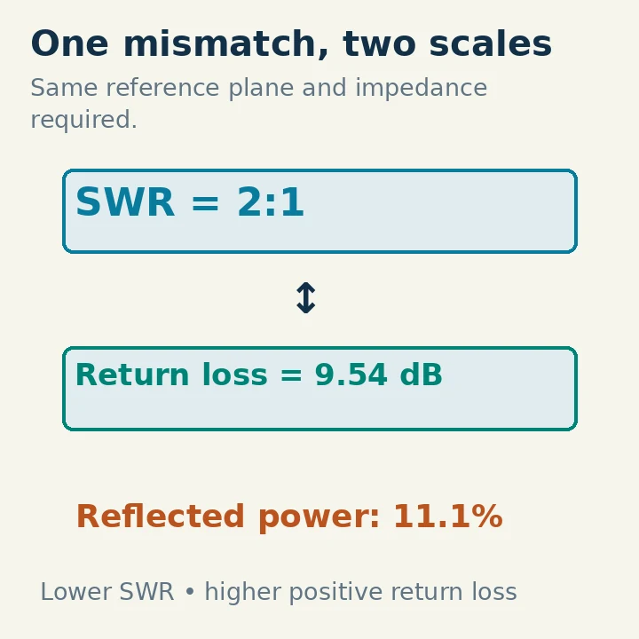
Do not identify the appropriate ratio solely by measuring SWR at the radio through a long feed line. The cable transforms impedance, and loss affects the measured mismatch. A tuner can further conceal the load from the transceiver. Establish the relevant reference plane before deciding what the transformer itself must handle.
Choose by the Actual Antenna Application
For a reasonably symmetrical coax-fed dipole whose feed-point impedance is already suitable, a documented 1:1 current choke is a plausible starting point for common-mode control. You are addressing a feed transition and unwanted current path, not assuming the dipole needs a large impedance transformation.
For a balanced high-impedance feeder feeding a tuner, the choice is more demanding. The impedance at the tuner end changes with antenna frequency and feeder length, sometimes greatly. A fixed-ratio balun should be selected for the tuner's architecture and the actual loads, including voltage and current extremes. An attractive SWR at the radio does not prove that a small core between tuner and feeder is operating comfortably.
For an end-fed system supplied with a documented unun or transformer, preserve the manufacturer's specified counterpoise and choke arrangement while establishing a baseline. If RF enters the shack or reception changes when the feed line moves, investigate common-mode behavior, grounding, routing and connections. Do not assume replacing a 9:1 device with a 4:1 balun is a general cure.
For a receive-only interference problem, a feed-line choke may reduce noise coupled through the feed line, but cannot remove noise arriving at the antenna as the wanted signal does. Compare receive readability and noise with a controlled arrangement. A quieter noise floor accompanied by equal loss of the wanted signal may not improve reception.
Check Power and Loss Separately from SWR
A rating should identify frequency, duty cycle and load conditions. Continuous digital transmission can heat a core differently from intermittent voice operation. A transformer that survives one short low-power test has not thereby qualified for prolonged high-power service.
Heating can result from core loss, high flux, excessive current, high voltage or a poor connection. Stop if the assembly shows unusual heating, odor, arcing or changing behavior. Do not touch exposed RF conductors during transmission or use your hand as a live current detector. Inspect and measure with transmission stopped.
Low SWR proves only that the measured port has a certain match. It does not prove low insertion loss, good common-mode suppression or efficient radiation. Loss itself can improve the apparent input match. W8JI's balun testing discussion treats transformation, loss and balance as separate performance questions, which is the useful approach for station evaluation.
For a home-built device, retain the core identification, winding diagram, cable type, intended bands and measurement method. A photo of a tidy box cannot substitute for these details. If measurements are unavailable, be explicit about that uncertainty rather than assigning a broadband power rating from appearance.
When comparing before and after results, preserve the antenna geometry and operating frequency as far as practical. Moving the cable while adding a choke can change the system too. Note those changes so an improved result is not assigned to one component without evidence.
A Practical Decision Sequence
First identify the antenna-side system as balanced or unbalanced and determine where the feeder connects. Then determine whether an impedance transformation is actually required at that point. Next, consider common-mode isolation and the return path. Finally, select a documented device for the resulting frequency range, power, duty cycle and load conditions.
Commission at low power, verify a reasonable match and compare behavior across the intended bands. Increase operating demands only within the documented limits. Record whether a change improved matching, reduced feed-line sensitivity or improved actual receive readability; those are different results.
You should be able to finish the sentence “This device is here to…” with a specific function. If the answer is transform 200 ohms toward 50 ohms, that describes a ratio. If it is impede current on the outside of the coax, that describes choking. If it is connect balanced and unbalanced systems appropriately, that describes the balun task. Keeping those functions explicit makes the labels useful.