Set up a Powerpole field-power lead by matching the contact to the wire, assembling the housings in a defined orientation, crimping and fully seating each contact, and verifying the completed lead before connecting a radio. The red and black shells make a useful visual convention, but only an electrical check establishes polarity. A correctly assembled connector also needs appropriately protected wiring upstream.
This guide covers ordinary low-voltage DC field power using the standard PP15/45 family. It does not cover mains wiring, high-voltage systems or every connector sold under the Powerpole name. Work with the battery and charger disconnected during assembly. If you are learning to crimp, practice on spare wire and contacts before making the lead you will use outdoors.
Choose the Contact, Wire and Tool as a Matched Set
The housing is only one part of the connector. The metal contact must match the conductor size, stranding and termination method, and the crimping tool must support that contact. Similar-looking PP15, PP30 and PP45 assemblies do not give every wire the same current capability. Anderson's datasheet gives contact-specific wire ranges and current/temperature conditions.
For one documented example, Anderson's closed-barrel 1331 contact is specified for 16–12 AWG wire. That establishes a contact/wire pairing, not the safe current of an entire homemade lead. Cable insulation, conductor length, bundled wiring, fuse, connectors and operating temperature all remain part of that decision. Do not trim strands from an oversized conductor to force it into a smaller barrel.
Choose genuine, traceable housings and contacts from a supplier that provides their instructions. Confirm that both mating halves use the same housing family: Anderson's finger-proof and standard PP15/45 housings are not interchangeable mating interfaces. Do not assume a red shell from another series will fit because the color is right.
For a first lead, a matched kit, the specified crimper, a wire stripper, cutters, a polarity-marked reference connector and a multimeter are more useful than a bag of unlabelled spare contacts. Select cable gauge and fuse ratings for the radio's maximum input current and the entire circuit. If that selection is unfamiliar, have an experienced station builder check the plan before energizing it.
Fix the Viewing Direction Before Joining the Housings
For the common ARES/RACES-style two-pole arrangement, look into the mating/contact face, with the wires pointing away from you. With the hood side up and tongue side down, red is on your left and black is on your right. Turn the assembly upside down and the mnemonic reverses. Look from the wire end and left/right also reverses. Always state the view, not merely “red on the right.”
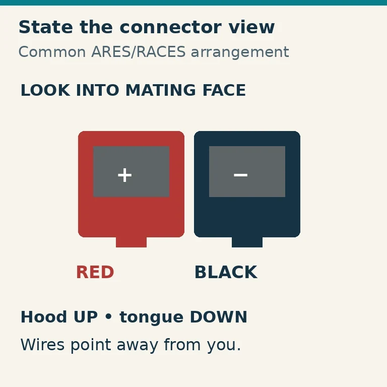
Compare with your club's actual standard or a known correct mating lead before assembling a whole collection. Housings can be paired in other arrangements for special applications; a mechanically mating pair is not proof of compatibility with a particular battery or distribution box.
Slide the housings together along their dovetails. Do not snap them sideways into place, hammer them or force a joint in the wrong direction. Powerwerx recommends joining the housings before inserting the contacts, particularly when the paired cable is stiff. Use the manufacturer's or supplier's appropriate housing-retention arrangement rather than leaving a pair that separates when handled.
Mark red as positive and black as negative for this station's low-voltage DC system. Check every adapter you intend to share. A color convention is an assembly target; it does not detect a previous owner's reversed battery lead.
Strip and Crimp Without Damaging the Contact
Separate only enough of a paired cable to position the two contacts without twisting the wires. Plan strain relief before cutting. If a boot or other part needs to slide onto the cable first, put it on now, while the cable is still disconnected from every power source.
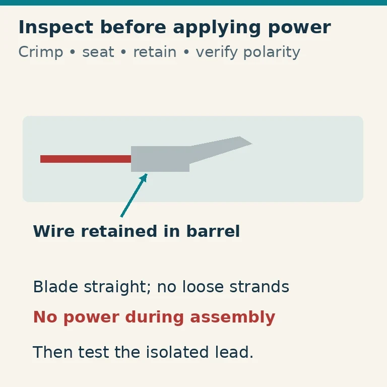
Use the strip length specified for the exact contact and termination tool. Remove insulation cleanly without cutting strands. The conductor should occupy the intended barrel area; insulation belongs outside the electrical crimp unless the selected contact has a separate insulation-support feature. Keep loose strands from extending toward the other pole.
Orient the metal contacts before crimping so they will enter their housings correctly. Put the wire fully into the barrel and use the specified crimper/die and full tool cycle. The contact blade should remain straight, and the barrel must retain the required profile to pass into the housing. A flattened or flared barrel can prevent full insertion even when the wire feels secure.
Inspect the termination under good light. Look for cut or escaped strands, insulation caught in the electrical crimp, an incomplete crimp, or a bent contact. Apply an appropriate gentle pull check to the wire/contact connection before insertion. Do not use the radio as a test load to discover whether a bad crimp happens to conduct.
If a contact is malformed, replace it and repeat the termination with the correct tool. Do not make trial repairs by crushing it with general-purpose pliers until it fits. Soldering is not a universal substitute: Anderson distinguishes open- and closed-barrel contacts and specifies that only the relevant closed-barrel contacts are suitable for soldering. For this beginner procedure, use an approved crimp system consistently.
Seat Each Contact and Check Retention
Insert the terminated contact from the wire side in its specified orientation. Powerwerx describes the contact passing over the housing's internal spring and clicking into place. Compare the contact position with a correctly assembled connector and the supplier's instructions; do not force a contact that stalls halfway.
A seated contact may float slightly in its housing. That small movement is different from a contact sliding backward out of the housing when you gently pull its wire. Inspect each pole from the mating face and gently check retention. If one sits farther back, will not latch or pulls free, stop and correct that assembly before connecting power.
Keep the two housings aligned as a pair. Use suitable retention and strain relief so cable movement does not turn into repeated force on the metal terminations. On a field lead, support heavy cable near the radio and distribution box; the contacts should not carry the weight of a battery hanging below a table.
Perform Isolated Electrical Checks First
With both ends disconnected from batteries, chargers and equipment, set the meter for continuity or resistance. Confirm that the intended positive path connects end to end and the negative path does the same. Confirm that positive and negative are not shorted together. Flex the lead gently while checking for an intermittent open connection.
For an adapter, do not check only the two colored housings. Trace each pole to the far connector's actual pin or terminal and compare that with the equipment manual. A barrel plug, cigarette-lighter adapter or battery harness introduces another polarity decision. Label an unusual adapter so the next operator does not infer its function from the shell colors.
Next, arrange a controlled live-voltage check without the radio attached. Switch the meter to DC volts, confirm the leads are in its voltage/common sockets, and choose a range appropriate to the supply. Never put a meter in current mode directly across a battery. With a suitably fused source connected, check the output using insulated probes or a proper test adapter that will not bridge adjacent contacts.
A positive reading with the red meter probe on the intended positive pole confirms that orientation at the measured output. A negative reading means the output polarity or probe placement needs investigation. Confirm the voltage is within the radio's permitted input range, then remove power before making further changes. Powerwerx explicitly emphasizes checking polarity before plugging equipment in.
Protect the Cable and Each Field Branch
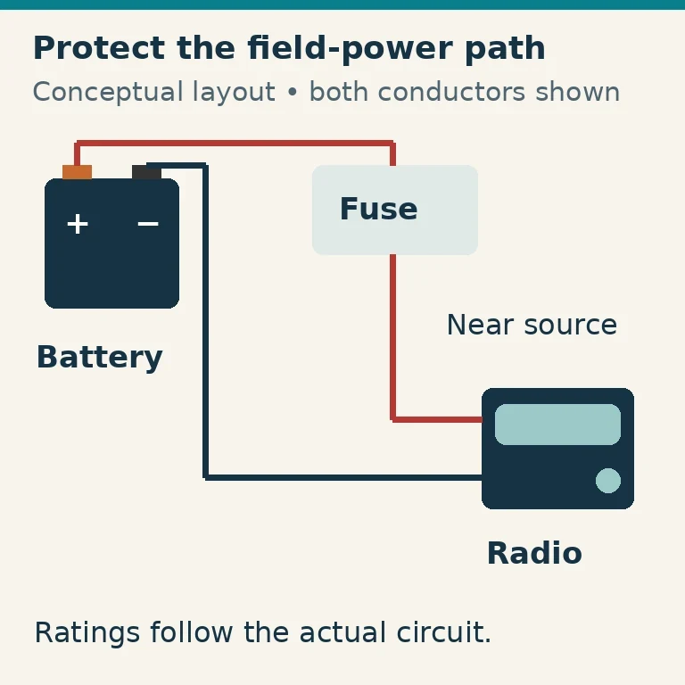
A fuse is intended to interrupt a fault before wiring overheats. Put source protection close enough to the battery to protect the outgoing lead, following the battery and equipment instructions. An otherwise correctly fused radio may leave a long battery lead unprotected if the only fuse is at the far end.
For a distribution box, give branches the protection appropriate to their wiring and loads. One large upstream fuse does not automatically protect a thin accessory cable. Likewise, a BMS's electronic protection does not replace a properly designed wiring-protection arrangement.
Do not choose the fuse by reading “45 A” on a connector package and assuming the whole lead is now a 45 A circuit. Use actual current requirements, wire ratings, length, voltage drop and manufacturer guidance. Keep the radio's specified fuse protection. Avoid improvised unfused terminal clips for a public field setup.
Test the Complete Station Before the Outing
Start with a short, controlled operating test using known good equipment and a correctly fused source. Monitor the radio's behavior and check for abnormal connector or cable heating. A connector that becomes unusually warm, a falling supply voltage or a radio that resets on transmit warrants a stop and inspection with power removed.
The same fault can have several causes: too-small wire, a long lead, a poor crimp, a contact not fully seated, an overloaded distribution point or a depleted battery. Repeatedly replacing a fuse with a larger one is not troubleshooting. Identify the limiting component before restoring operation.
Label the finished lead with polarity, purpose and any relevant rating or restriction. Cap unused live connectors and carry them where metal tools cannot enter the mating face. Keep the assembly dry unless its specific enclosure is rated for the exposure. Before separating connectors, switch off the load and grasp the housings rather than pulling on the cable.
Your completed field-power lead should pass four checks: the intended mechanical orientation, secure contacts, correct end-to-end polarity and voltage, and protection suitable for its actual circuit. Retain one verified reference lead with your station kit so the next assembly starts from an established standard.