Choose a bandpass filter by the unwanted signal you need to reject, the frequencies you need to pass and the power it must handle. A filter that works well ahead of a receiver may fail in a transmitting path. A high-power filter can still be the wrong choice if its passband, rejection or installation position does not address your problem.
Begin by identifying the problem at the station. Then select specifications and a location in the signal chain. Buying a filter simply labeled “HF” or “low SWR” leaves too much unanswered.
Decide Whether a Bandpass Filter Addresses the Problem
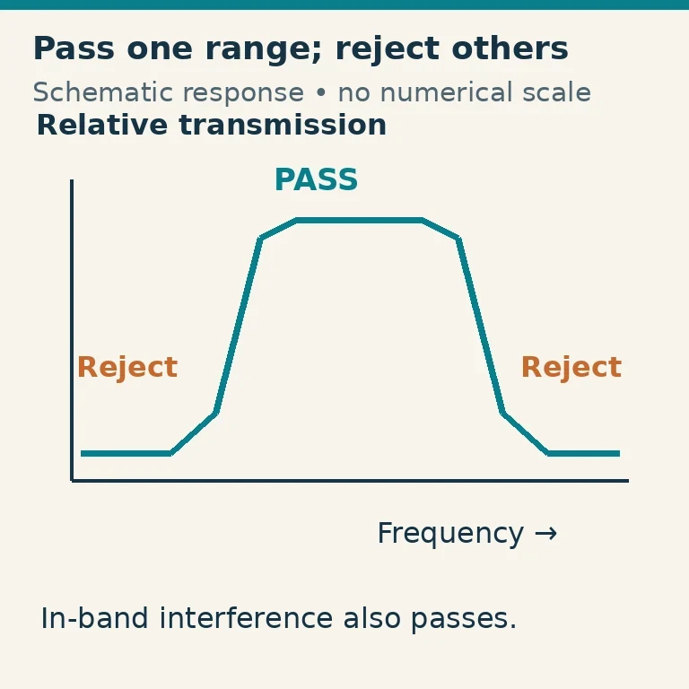
A bandpass filter passes a selected frequency range and attenuates frequencies outside it. In amateur operation, an external band filter commonly passes one amateur band while reducing energy from other bands.
That can help a receiver suffering from a strong out-of-band signal or reduce interaction between nearby stations on different bands. It does not normally remove interference already inside its passband. Two strong stations a few kilohertz apart on the same band may both pass through the filter almost unchanged.
Do not confuse an external RF bandpass filter with a receiver's narrower IF, roofing or audio filters. Those operate at different points and bandwidths to select the wanted channel or audio. An external band filter cannot reproduce every benefit of filtering earlier or later inside the receiver.
A low-pass filter passes frequencies below its cutoff and is often used for harmonic suppression. A notch filter rejects a narrower unwanted range. If one strong broadcast signal is the problem, an appropriate notch or broadcast-rejection filter may fit better than a set of amateur-band filters.
Before buying, try the receiver's attenuator or preamplifier settings and inspect the antenna/feedline system. Improvement with attenuation can suggest overload, but it is not a complete diagnosis. Noise carried on feedlines, a defective connection and an on-frequency interferer require different remedies.
Write Down the Wanted and Unwanted Frequencies
Record the band and mode you want to use, plus the frequency and likely strength of the unwanted signal. For a multi-radio station, list which transmit band threatens which receive band. Rejection is frequency-dependent; “40 dB rejection” means little without the frequency where it applies.
Make a small requirements table before comparing products:
| Requirement | What to specify |
|---|---|
| Wanted range | Actual band edges needed, including local allocation and operating frequencies |
| Unwanted range | Nearby station, broadcast source, harmonic or other identified frequency |
| Passband loss | Maximum acceptable insertion loss across the wanted range |
| Rejection | Required attenuation at each important unwanted frequency |
| Power | Actual carrier/PEP, mode duty, duration and mismatch conditions |
| Interface | Impedance, connectors, switching method and installation environment |
A filter advertised for “20 meters” may have excellent performance at one point and different loss near an edge. Look for a response curve or a table covering the whole needed range. Check whether a multiband unit includes WARC bands; a six-band contest filter is not automatically a nine-band HF filter.
Manufacturer plots can be useful evidence, but distinguish typical curves from guaranteed limits. Avoid treating a marketing superlative as a comparative laboratory result.
Read Insertion Loss and Rejection Together
Insertion loss is the wanted-signal reduction caused by adding the filter under stated conditions. Lower is generally preferable, but compare it over the passband and at the intended impedance.
A 0.5 dB insertion loss delivers about 89% of the input power to a matched load; 1 dB delivers about 79%. For an illustrative 100-watt input, those are roughly 89 and 79 watts. The difference is dissipated or otherwise lost within the real network under its specified conditions; it must not be ignored when considering heat.
Rejection describes attenuation at an unwanted frequency. A 30 dB reduction corresponds to a thousandfold power ratio, but the remaining signal may still be strong. Reducing an extremely strong nearby transmitter does not guarantee a sensitive receiver is safe or free of overload.
Check the filter's transition region. A broad passband may have little rejection just outside the amateur band. A narrow passband can give sharper separation while risking greater loss or mismatch near your wanted edge.
Measurements should use the stated reference impedance and appropriate test setup. A response measured between well-matched 50-ohm ports may change when connected to a badly mismatched antenna. The response plot is not a promise for every load.
Match the Power Rating to the Mode
A receive-only filter must not be placed where it will encounter transmitted power unless its manufacturer explicitly rates that use. A preselector designed for a receiver input is not interchangeable with a transmitter filter just because both have coax connectors.
For transmitting, look for a clear power rating with mode and duty conditions. A PEP rating intended for intermittent SSB does not establish suitability for a long digital carrier. WSPR, RTTY and other sustained transmissions can impose much greater heating than casual voice at the same peak power.
As a concrete example, the Array Solutions AS-419 Bandpasser II manual specifies its own 100-watt, 100% duty-cycle RTTY capability and other operating conditions. That is evidence about that unit, not permission to run 100 watts through every amateur filter. Read the exact model's manual.
Check cooling, ambient temperature, maximum operating duration and mismatch limits. Internal component voltage and current can rise sharply with an unsuitable load. Reducing average transmission time does not necessarily prevent a high-voltage failure at a peak.
If an amplifier follows the filter, determine the drive-level power passing through it. If the filter is after the amplifier, it must be explicitly rated for the amplifier's actual output, mode and load. A 100-watt filter is not protected by its location near a 1,000-watt amplifier.
Put the Filter in the Correct Place
For many drive-level transmitting filters, a typical position is between transceiver and amplifier. The amplifier's required output filtering remains necessary. Do not assume an input bandpass filter makes the amplified output spectrally clean under every operating condition.
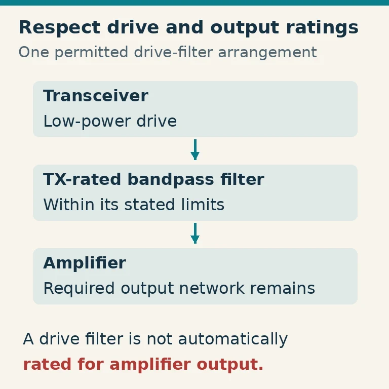
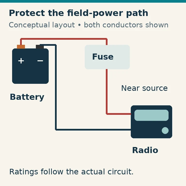
The AS-419 manual specifically describes placement between transceiver and amplifier and warns against using that unit at amplifier output. It also includes instructions about tuners and mismatched loads. Follow the actual unit's permitted topology rather than treating the accompanying conceptual chain as a universal wiring diagram.
A tuner inside the transceiver can present an acceptable load to the transmitter while leaving the external filter exposed to an unsuitable impedance. A low SWR displayed at the radio therefore does not prove the filter is operating under its rated conditions.
An external tuner can change which part of the path sees mismatch, depending on its position. Read the filter, tuner and amplifier manuals together. Do not run an automatic tune cycle through a filter if the manufacturer prohibits it.
At a receiving-only station, a filter ahead of the vulnerable receiver input may be useful. In a transceiver station, a receive-path filter needs a suitable transmit bypass or protected receive-only port. Verify that arrangement rather than relying on memory before pressing PTT.
Check Switching and Band Coordination
Manual single-band filters are simple when you operate one band for a session. Switched banks suit frequent band changes, but add the need for correct selection, control wiring and interlocks.
Selecting the wrong band can produce substantial loss, mismatch or component stress. Check the indicated filter against the radio before transmitting. Automatic band data is helpful only when the radio, interface and filter agree on the encoding and supported bands.
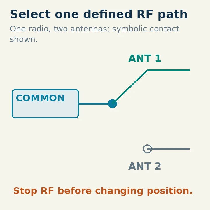
Avoid hot switching unless the equipment explicitly allows it. Stop RF, select the correct path and verify readiness before applying power. A relay's contact rating and control timing matter as well as its nominal frequency range.
For a multi-radio station, coordinate band assignments and power changes. Filters are one part of isolation alongside antenna spacing, feedline arrangement, receiver protection and operating practices. Do not use a rejection number alone to calculate a supposedly safe station separation.
Inspect and Test Before Full-power Operation
Check connectors, impedance and mechanical support. Heavy adapters hanging from small sockets can damage equipment even when their RF specifications look acceptable. For portable use, protect the unit from rain and strain without blocking required cooling.
If you have suitable equipment, inspect passband loss, rejection and return loss with a network analyzer at low signal level. Calibrate at the relevant reference planes and compare with the manufacturer's conditions. A basic SWR meter alone cannot establish stopband rejection.
Begin transmitting at low power into an appropriate load or correctly configured antenna system. Confirm the selected band, forward/reflected behavior and permitted operating conditions. Increase only within the documented rating, watching for unexpected heating, odor, instability or changing loss. Stop if behavior is abnormal.
Do not infer transmitter-power capability from a successful low-level analyzer sweep. It checks a different property. Likewise, a cool enclosure after a short voice test does not establish continuous-carrier suitability.
Make the Final Choice from the Requirement, Not the Label
For a single-band portable station, a compact manual filter may be enough if its rating and purpose match the actual interference problem. For a multi-band or multi-operator station, a properly coordinated bank may justify the added complexity.
Prefer a unit with documented passband edges, loss, rejection at your unwanted frequencies, power/duty limits and installation instructions. If those details are missing, ask the maker before using it in a transmitting path.
After installation, repeat the original interference test under comparable conditions. Record what improved and what remains. A useful filter solves a defined station problem while preserving the wanted path; it does not need to promise a universally quieter band.