To tune an antenna, first measure its standing wave ratio (SWR) at low power on the frequency you intend to use. If the antenna’s instructions permit an adjustment, change one thing with transmission stopped, then measure again. If physical adjustment is unavailable or unsuitable, a compatible antenna tuner may improve the match the radio sees. Those are different results: a good SWR reading at the radio does not, by itself, show that the antenna radiates efficiently.
This guide is for a U.S. operator with an installed or kit antenna and a way to read SWR. Before any test transmission, confirm that the frequency is clear and within your license privileges. For the actual connections, meter procedure, test power, adjustments and matching limits, use the manuals for your antenna, radio, meter and tuner.
Understand Which Part of the Antenna System You Are Tuning
Picture the system in this order:
Radio → optional tuner → feed line → antenna
The feed line carries the radio-frequency signal to the antenna. SWR describes a match at the point where it is measured. When you change a manufacturer-permitted part of the antenna or its deployment, you are changing the antenna system itself. You can then measure whether that particular change improved the reading where you are testing. When you operate an antenna tuner, you are instead matching the antenna system to the impedance the radio expects to see. ARRL describes that expected transceiver impedance as 50 ohms.
The meter’s location matters. A reading displayed by the radio is a reading at the radio side of the system; it is not a measurement of how much signal leaves the antenna. The lowest SWR you observe in a set of readings is useful for comparison, but it does not establish zero reactance or prove antenna efficiency.
This distinction is especially important when a tuner sits near the radio. ARRL explains that matching the system there does not change the SWR between the tuner and the antenna. It also warns that elevated SWR on that side can cause some power to be lost as heat before reaching the antenna. A successful tuner adjustment can therefore protect the narrower conclusion that the radio sees a better match—not the broader claim that feed-line loss is low or radiation is strong.
There are two practical paths through the rest of the guide. If your antenna instructions allow a physical or deployment change, compare readings before and after one such change. If the antenna is installed as intended and a compatible tuner is the appropriate available way to match it to the radio, use the tuner within its documented limits. Neither path calls for guessing at a wire length, cutting from a sample reading or adjusting a conductor while transmitting.
Prepare a Safe, Repeatable SWR Measurement
Start by identifying the frequency where you actually want to operate. Confirm that the installed antenna is assembled and deployed as its instructions require. With transmit power off, check only connections you can reach safely: for example, whether the feed-line and meter connections are seated in their intended positions. Do not climb, approach a hazardous installation or disturb antenna conductors to make a test.
Next, confirm two conditions before transmitting: your U.S. license privileges permit transmission on the chosen test frequency, and the frequency is clear. If you plan to compare readings on frequencies around your intended one, each test frequency needs the same check. Receiving a signal or seeing a frequency on a radio display is not, on its own, permission to transmit there.
Choose the measurement arrangement specified for your equipment. In its end-fed half-wave (EFHW) kit instructions, ARRL gives two ways to test that antenna: use the transceiver’s SWR meter, or connect an external SWR meter in the feed line between the transceiver and the kit’s impedance transformer. That is a connection example for that kit, not a universal location for every external meter. Follow your antenna, radio and meter manuals for the correct placement, calibration if required, permitted test power and method of taking a reading.
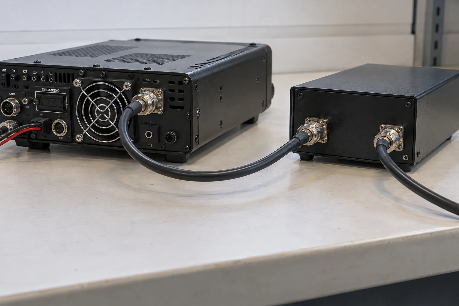
Set the low test power permitted by those manuals; ARRL specifically calls for low power in its antenna-kit test. Before recording a number, note whether a tuner is in the path and whether the display is showing the match on the radio side of it. If you are comparing antenna adjustments, keep the meter position and tuner state consistent. Bypass a tuner for that comparison only if your installed equipment provides and permits a bypass. Otherwise, document its state rather than treating unlike readings as directly comparable.
Make your record simple enough to repeat: frequency, SWR, tuner state, meter location and antenna configuration. You do not need to chase a perfect-looking number on the first transmission. You need a trustworthy baseline taken under a setup you can reproduce.
Stop transmitting before touching the antenna. Make it safe before any permitted element or deployment change, and leave installation work beyond your safe reach to someone qualified. Measurements are made with the equipment operating as its instructions require; adjustments to conductors are not live-work steps.
Measure the Pattern, Then Adjust Only What the Antenna Permits
A single SWR reading tells you less than a short, repeatable sweep. Using the equipment’s transmission and meter instructions, take low-power readings at several clear frequencies on which you are authorized to transmit: include the intended operating frequency and suitable points on either side of it. Keep the antenna configuration, meter arrangement, tuner state and test procedure the same throughout that set. Write down each frequency beside its reading.
Look for the lowest observed reading among the points you tested, then compare its frequency with the one you want to use. That tells you where the better match appeared in this particular set of measurements. It does not prove that you found the absolute minimum between test points, that reactance is zero or that the antenna is efficient. It gives you a baseline against which to judge a permitted change.
Here is an illustrative comparison, not a target SWR or an instruction to change antenna length. The frequency positions stand for five specific, clear and authorized frequencies that an operator would write in their own log.
| Test point | Before change | After one permitted change |
|---|---|---|
| Farther below desired frequency | 2.0:1 | 2.3:1 |
| Slightly below desired frequency | 1.4:1 | 1.7:1 |
| Desired frequency | 1.7:1 | 1.3:1 |
| Slightly above desired frequency | 2.2:1 | 1.6:1 |
| Farther above desired frequency | 2.8:1 | 2.1:1 |
In the before sweep, the lowest recorded reading is slightly below the desired frequency. In the after sweep, the lowest recorded reading is at the desired frequency, and its reading there has changed from 1.7:1 to 1.3:1. For the goal of improving the recorded match at that desired frequency, this example change helped. It did not improve every test point: the two readings below the desired frequency went up. That is why the useful comparison is a fresh sweep at the same points, not one favorable number chosen after the fact. The example says nothing about which direction to move, deploy or trim a real antenna.
To make your own before-and-after comparison, consult the installed antenna’s instructions first. If they permit an element or deployment adjustment you can perform safely, stop transmission, change one permitted variable and record exactly what changed. Then restore the measurement setup and repeat the low-power readings at the same frequencies. Changing one variable gives you a clearer comparison than altering several things and trying to guess which one mattered.
If the new sweep improves the reading you care about, check that the resulting configuration still follows the antenna instructions before retaining it. If it does not help, do not assume that a larger version of the same change will. Return to the documented options or seek model-specific guidance. If the instructions do not permit a physical change, leave the element alone; consider the compatible-tuner path below instead.
ARRL’s EFHW kit illustrates why design-specific directions matter. Its instructions tell builders to try different antenna configurations before trimming wire. For that kit, ARRL then describes trimming a couple of inches at a time to seek low SWR on its bands. That is advice for the documented kit, not a cutting increment—or even permission to cut—for another antenna. An irreversible cut cannot be justified by the illustrative table above.
Likewise, ARRL calls approximately 1.5:1 or lower a good match in its antenna-kit example. Do not turn that figure into a universal pass mark for your radio, tuner or antenna. Use the installed model’s instructions to judge what is acceptable, and use your recorded readings to judge whether the particular allowed change moved your measured result in a useful direction.
Use a Compatible Tuner When Matching at the Radio Is the Right Path
A tuner is the alternative when the antenna system is installed as intended but the match presented to the radio calls for matching, and the particular radio and tuner instructions permit the antenna, frequency, connection, power and matching range involved. It is not a substitute for checking an incorrectly assembled antenna or an unsafe connection. Nor is every tuner interchangeable: the installed models’ instructions govern how they connect and operate.
For an automatic tuner, first set up the radio and tuner as their manuals specify and use the prescribed low power. ARRL notes that, depending on the design, an automatic tuner may begin working when RF power is applied or when a button is pressed. Initiate only your model’s prescribed cycle, then check the resulting SWR reading on the radio side. ARRL’s low-power caution applies to automatic tuners too. If the cycle does not complete as the manual describes, do not keep increasing power or repeatedly trying to force a result.
A manual tuner requires you to adjust its controls yourself. ARRL gives a useful example of the sequence: while receiving, adjust the tuner controls for maximum noise; then transmit a small amount of power while watching the SWR meter and adjust the controls to reduce the reading. Once you find useful settings, write them down so you can return to them. ARRL mentions roughly 10 W in that example, but it is not permission to use that power with your equipment, nor a required tuning setting. Follow the permitted low-power procedure in your actual radio, meter and tuner manuals.
Check matching limits before interpreting an unsuccessful attempt. ARRL says built-in radio tuners are limited and usually handle SWR only up to about 3:1. That general description is not your radio’s specified limit; find that in its manual. Equipment power ratings are model-specific too: Icom lists 120 W PEP as the maximum input for its AH-4. That ceiling is not a recommended tuning power and says nothing about the limit of a different tuner.
After either type of tuner operates, recheck the radio-side reading at the frequency where you intend to transmit. A lower reading there establishes the practical result you were seeking from the tuner: an improved match seen by the radio under that setup. Keep the distinction from physical antenna adjustment in view. ARRL says SWR between a tuner and antenna remains unchanged by tuning at the radio, and power can still be lost on that side. The result does not certify low feed-line loss or efficient radiation.
Respond When the Reading Stays High or Matching Fails
If a sweep remains unfavorable after an allowed antenna change, stop transmitting before investigating. Recheck accessible connections with power off and compare the antenna’s actual configuration with its instructions. Correct only a documented issue that you can address safely, then repeat the low-power comparison under the same measurement arrangement. For ARRL’s EFHW kit, trying its documented configurations before any trimming is the relevant example; another antenna needs its own directions.
If an automatic tuner will not complete its prescribed cycle, a manual tuner will not produce an acceptable reading, or SWR remains high, stop repeated attempts. Consult the specific radio and tuner manuals for their matching limits and failure indications. Do not raise test power to force a match. A tuner that cannot match the installed system within its limits is a reason to seek model-specific help, not to improvise an antenna alteration.
The outcomes call for different conclusions. An allowed antenna change that improves your recorded reading at the desired frequency may be retained if it remains within the antenna instructions; recheck it in its final configuration. A successful tuner cycle supports the narrower conclusion that the radio sees a better match. If neither path produces an acceptable result within the equipment’s documented limits, stop transmitting and get help with that specific system.
The working rule is straightforward: measure safely at low power, change only an allowed antenna variable or use a compatible tuner, then recheck at your intended frequency. Stop when the system will not match within its instructions. Even a pleasingly low SWR is a match reading—not a guarantee of a strong radiated signal.