The Short Answer: Choose the Reading Your Work Requires
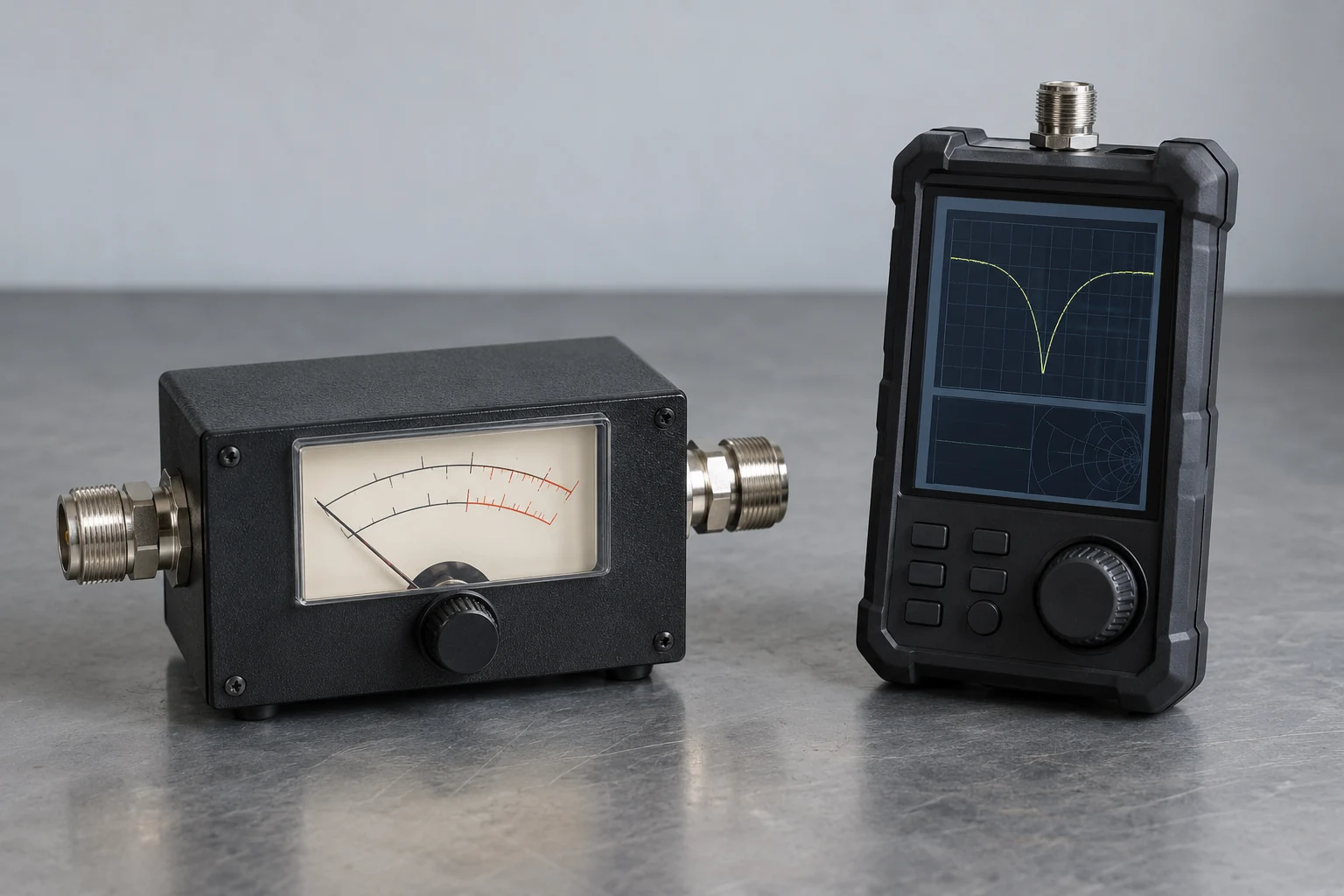
For routine checks while transmitting, start with a suitable SWR readout you already have. If you need a separate station display of SWR and power, consider an inline SWR meter. If your work involves repeated antenna adjustment or diagnosis without transmitting, an Antenna analyzer is the more relevant tool to consider. The choice is about the reading your task requires, not which device has the longer feature list.
Here, “SWR meter” means an inline transmitting-station SWR/power meter, although some transceivers and tuners provide an equivalent SWR readout. That distinction matters if you already have a usable display: adding another meter may not answer a new question. Conversely, a station readout need not replace the information you want when working on an antenna away from routine operating checks.
The models discussed below are examples for comparing capabilities, not promises that every meter or analyzer has the same functions.
How Each Tool Gets a Reading—and Where It Connects Safely
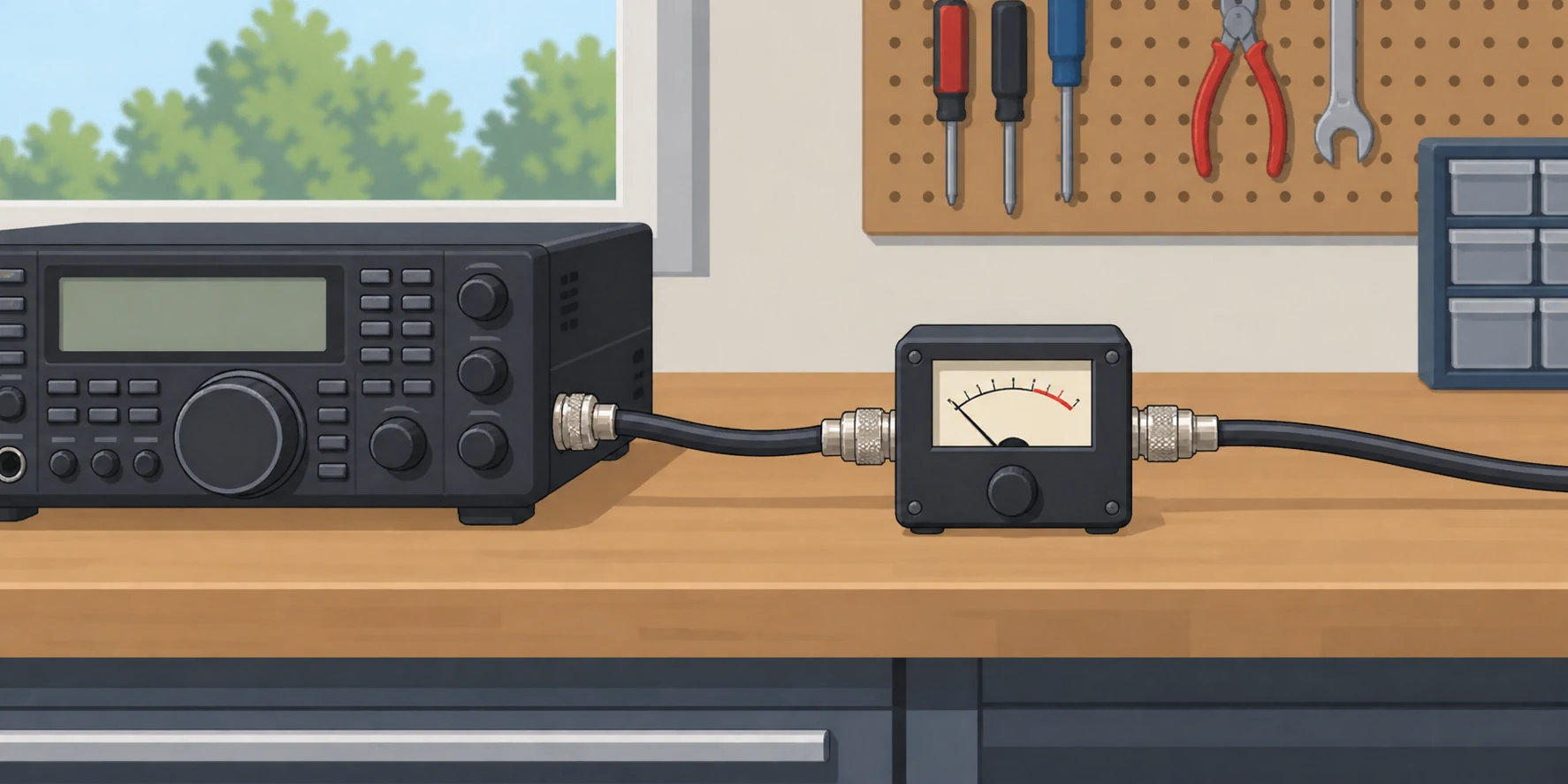
An inline SWR meter observes the station’s signal while the radio transmits. In ARRL’s meter-based antenna-adjustment example, the operator sends a low-power station signal and watches the SWR reading. The MFJ PM-30, for example, displays forward power, reflected power, and SWR in a transmitting-station setup. The connection is radio → inline meter → feed line and antenna. The meter needs a station signal to report a reading; connecting it alone does not generate one.
An antenna analyzer instead supplies its own low-power test signal. ARRL describes analyzers as battery-operated low-power transmitters and distinguishes their generated signal from the station radio’s transmission. RigExpert lists the Stick 500’s test output as −10 dBm into a 50-ohm load; that is an example, not a specification for every analyzer. For an antenna check, the analyzer connects to the antenna or feed line under test in place of the transmitting radio. It is not another device to insert into the live transmit path.
“Without transmitting” in this context means without using the station radio to transmit. The analyzer still generates a test signal. Its ability to supply that signal does not mean its input can accept transmitter power, just as an inline meter’s ability to observe transmitter power does not make it a substitute for the analyzer’s signal source.
That difference matters when changing hookups. If you have been checking SWR with the station radio, stop transmitting and disconnect the radio from the antenna path before connecting an analyzer to the path you want to examine. Keep the transmitter off that connection while the analyzer is attached. MFJ explicitly warns not to connect a transmitter to its analyzer’s antenna jack. Never attach an active transmitter to an analyzer input. Before transmitting again, remove the analyzer and restore the intended station connection. Merely switching the analyzer off is not a substitute for keeping transmitter power away from its input.
Consider an antenna adjustment at the station. With an inline meter, you make a brief, low-power transmission and observe the reading during that transmission, as in ARRL’s example. To use an analyzer instead, you stop using the radio as the signal source, separate it from the antenna path, and connect the analyzer to the path being checked. Both hookups can produce an SWR-related reading, but only the meter hookup carries the station’s transmitting signal.
What the Readings Can Tell You During Tuning and Diagnosis
An SWR meter answers an operating question: what SWR is the station seeing while you transmit? A radio or tuner readout may already provide that number, and a stand-alone meter can monitor it too. The MFJ PM-30, for example, displays forward and reflected power as well as SWR, so its readings can show both the power being sent and the power reflected at that measurement point. Those are useful observations during normal operation, but a single reading at one frequency does not show where SWR would be lower elsewhere in the range.
An antenna analyzer can make the frequency pattern visible. The RigExpert Stick 500 shows an SWR chart across a chosen range and reports the minimum; ARRL describes a sweep display as showing the highs and lows across many frequencies. Suppose you adjust an antenna for one intended operating frequency, but the chart’s lowest SWR appears well below it. That tells you more than the operating-frequency number alone: the low point is elsewhere, so another adjustment may be warranted. If the dip is already near the intended frequency, chasing a lower number at a different frequency may not serve the operating goal. The sweep shows where the change occurs, not just whether one reading improved.
Impedance readings add another diagnostic distinction. ARRL notes that analyzer impedance information includes resistive and reactive values; the MFJ-259C, specifically, presents resistance, reactance, impedance and SWR in its basic measurement function. If two adjustments produce a similar SWR at the frequency of interest, those additional values let you compare what changed rather than treating the SWR figures as the whole story. A change mainly in reactance is different evidence from a change mainly in resistance. Neither value, by itself, identifies the physical cause of a problem, but the separation can help narrow what an adjustment accomplished.
That distinction matters when a low SWR reading tempts you to stop diagnosing. For routine observation, the operating number and, where available, power readings may be all the information the task calls for. When an adjustment keeps moving the best-SWR frequency unexpectedly, a sweep gives you a way to follow that movement; when SWR changes without making the reason clear, resistance and reactance provide another view. These are different questions, not simply a contest over which instrument displays more numbers.
Finally, do not assume every analyzer can locate a fault along a cable. ARRL says only a few analyzers offer time-domain reflectometry, or TDR, fault-location functions. A sweep or impedance display can inform diagnosis without providing a distance to a fault; that specific capability depends on the analyzer.
Match the Tool to How Often and Where You Work
For routine station monitoring, start with the readout you already use. A radio’s built-in display, a tuner readout or a stand-alone SWR meter can monitor antenna-system SWR . If that answers the question you regularly ask while transmitting, another instrument may add little to the task. A dedicated meter has a clearer purpose when you want a separate station display of both SWR and power: the MFJ PM-30, for example, displays forward power, reflected power and SWR . That is a reason to add a meter for ongoing monitoring, rather than a reason to replace every existing readout.
The work pattern changes when you are altering an antenna. ARRL notes that adjusting a dipole using meter-only SWR checks can mean repeated changes to the wire followed by more checks . If you expect to do that regularly, a plotted view can make each adjustment more informative. The RigExpert Stick 500’s Free mode, for example, offers a user-selected wide or narrow frequency plot . A wide view can help you see where an adjustment has moved the area of interest; a narrower view can help you focus on the part you are trying to refine. The advantage matters most when you will use that information repeatedly, not merely because a plot is available.
Field work presents a similar tradeoff in a different setting. RigExpert describes the Stick 500 as compact and suitable for home and field use . That makes it an example of an analyzer intended to travel with an antenna-adjustment project. But a portable instrument is only useful if the work calls for its measurements: someone operating from a settled field setup and checking station SWR has a different task from someone changing an antenna each time they go out. Choose the amount of equipment to carry around the work you expect to do there.
Frequency of use also changes the case for ownership. ARRL says analyzer impedance information is useful for recurring antenna design or modification, but that owning an analyzer may not be justified if you do not plan to experiment with antennas . For occasional troubleshooting—say, a one-off question about an antenna you otherwise leave alone—club loan or joint ownership is an access option ARRL explicitly suggests . Borrowing or sharing lets you use the additional information when a project calls for it without making that project an everyday station expense. The tradeoff is access: a shared instrument must be available when you need to work, whereas an owned one is on hand for repeated sessions.
These are not competing purchases on a single ladder. Station monitoring, repeated adjustment and occasional diagnosis are different jobs. An existing readout can remain useful even if you sometimes borrow an analyzer; a dedicated meter can remain useful even if you own one. The practical question for this section is how often you need each kind of reading, and whether that need arises at the operating position, alongside an antenna project or only occasionally.
Check Fit—and the Limits of a Good-looking Reading
Start with the frequency you intend to measure, not the tool’s name. The MFJ PM-30 inline meter is specified for 1.8–60 MHz, while the RigExpert Stick 500 antenna analyzer is specified for 100 kHz–500 MHz. Those are specifications for two particular models, not promises about every meter or analyzer. For example, 144 MHz falls within the Stick 500’s stated range but outside the PM-30’s; an operator working there would need a different inline meter for transmitting-station monitoring. Analyzer coverage also varies by model. Conversely, an analyzer’s stated frequency range does not tell you whether a particular inline meter suits your transmitter. Check each instrument against the job you want it to perform.
For an inline meter, check the transmitter power against the actual handling specification of the model under consideration. The PM-30 lists 300-W and 3000-W scales, but a scale marking alone should not be treated as proof that every station setup is suitable. Both the PM-30 and Stick 500 specify SO-239 connectors, so a plan to use either one must account for the connectors already on the intended cable and measurement point. Their shared connector type does not make the two instruments interchangeable: frequency coverage, power compatibility where transmission is involved, and the reading needed still differ. If the intended connection point is not the one you first pictured, reassess fit there rather than assuming a connector match elsewhere in the station settles it.
Where the reading is taken matters as much as the number. An SWR indication at the radio or station describes the path seen from that measurement point; it does not automatically describe every component farther along the line. ARRL therefore advises checking the actual station path. If a tuner sits between the radio and antenna, note which side of it supplies the reading before interpreting a low SWR. A built-in radio readout may answer whether the radio sees an acceptable match, yet leave a different question—what is happening beyond the tuner—unanswered.
A tuner can present a low SWR to the radio while leaving the SWR between the tuner and antenna unchanged. Thus, a reassuring radio-side display after tuning tells you about the match presented to the radio, not that the antenna-side path has become well matched. This distinction is especially important when a previously troublesome antenna appears “fixed” solely because the tuner now finds a setting the transmitter accepts. Comparing readings without identifying whether they come from the same side of the tuner can make a change in measurement point look like a change in the antenna-side match.
Nor is low SWR a complete verdict on antenna performance. ARRL describes SWR as only part of that story, and MFJ cautions that an analyzer’s match-efficiency reading concerns forward and reflected power on the feed line—not power radiated by the antenna. A favorable display can help answer a matching question at a defined point, but it cannot by itself establish radiated efficiency. Keep the claim as narrow as the measurement: identify the frequency, the point in the station path, and what the displayed quantity actually represents.
Which Should You Use?
If routine operating checks are the job, start with the SWR readout you already have. Add a dedicated SWR meter when you need separate station SWR and power monitoring, rather than buying another instrument to answer the same question. If antenna adjustment or diagnosis is recurring work, owning an Antenna analyzer may be worth the access it gives you when you need it. For an occasional project, borrowing or sharing one may serve just as well.
The dividing line is not which tool costs less or displays more information. It is whether the readings you need are available at the point in your work where you need them. A station monitor earns its place through repeated operating use; an analyzer earns its place through repeated adjustment or diagnostic use. Choose the arrangement that fits your work pattern and station, including existing equipment and realistic access to a shared tool.