Call and
Signal
Menu

Beginner guides

Guides

Beginner amateur-radio guidance for the United States, with current-rule checks, realistic equipment choices, and clear safety stop points.

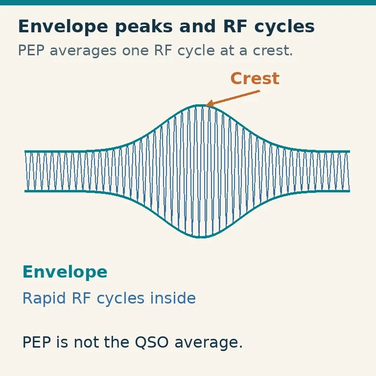
A changing envelope around rapid RF cycles, identifying the envelope crest where PEP is defined rather than the average over a conversation.
Choosing a Radio · 6 min

PEP Power and Duty Cycle in Amateur Radio Explained

PEP describes the power at the crest of a signal's modulation envelope; duty cycle describes how much of a stated time interval is spent transmitting. They answer different questions. A station can produce 100 W PEP while averaging much less RF power over a conversation, yet a long digital transmission can impose a demanding heat load even when transmissions occur only occasionally.

Read guide →
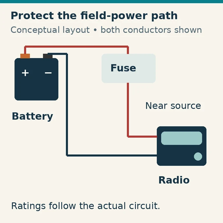
A conceptual two-conductor field-power circuit with a fuse near the battery in the positive path and a return path to the radio.
Station Setup · 8 min

How to Set Up Anderson Powerpole Connectors for Field Power

Set up a Powerpole field-power lead by matching the contact to the wire, assembling the housings in a defined orientation, crimping and fully seating each contact, and verifying the completed lead before connecting a radio. The red and black shells make a useful visual convention, but only an electrical check establishes polarity. A correctly assembled connector also needs appropriately protected wiring upstream.

Read guide →
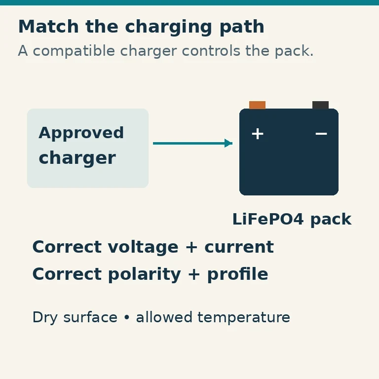
A matched charger feeding a LiFePO4 pack, with voltage, current, polarity, profile and temperature conditions identified.
Troubleshooting and Safety · 8 min

How to Charge LiFePO4 Batteries Safely for Ham Radio

Charge a finished LiFePO4 radio battery with a charger explicitly approved for that pack's chemistry, series-cell count, charge voltage and current. Check the pack's charging-temperature limits before connecting it, confirm polarity, and charge on a dry, stable surface away from combustible material. A plug that fits, a “12 V” label or a built-in battery management system does not establish that a charger is suitable.

Read guide →
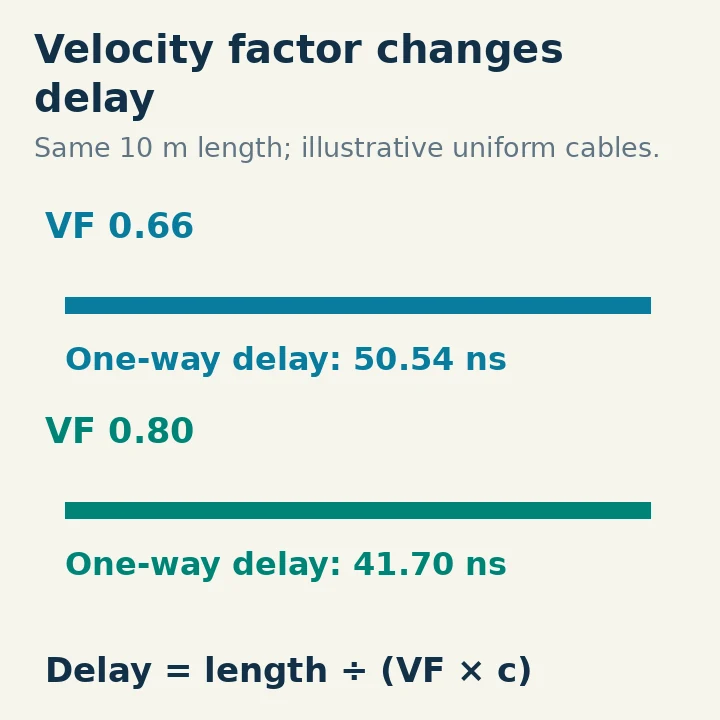
Two hypothetical uniform 10-meter cables have velocity factors 0.66 and 0.80, producing one-way delays of about 50.54 and 41.70 nanoseconds respectively; these are illustrative values, not product specifications.
Antennas and Feed Lines · 8 min

Understanding Coaxial Cable Velocity Factor

Velocity factor is the speed of a wave in a transmission line divided by the speed of light in vacuum. A coaxial cable with a velocity factor of 0.66 carries the relevant wave at about 66% of that vacuum speed. At a given frequency, its wavelength inside the cable is also about 66% of the free-space wavelength.

Read guide →
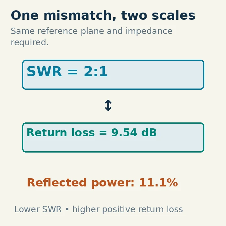
At the same reference plane, 2-to-1 SWR equals about 9.54 decibels positive return loss and 11.1 percent reflected power.
Antennas and Feed Lines · 7 min

SWR vs Return Loss: Understanding the Difference

SWR and return loss describe the same port mismatch using different scales. Lower SWR is better, with a perfect match at 1:1. Higher positive return loss is better, with a perfect match approaching infinity in the ideal calculation. A 2:1 SWR corresponds to about 9.54 dB return loss and 11.1% reflected power at the same reference plane.

Read guide →
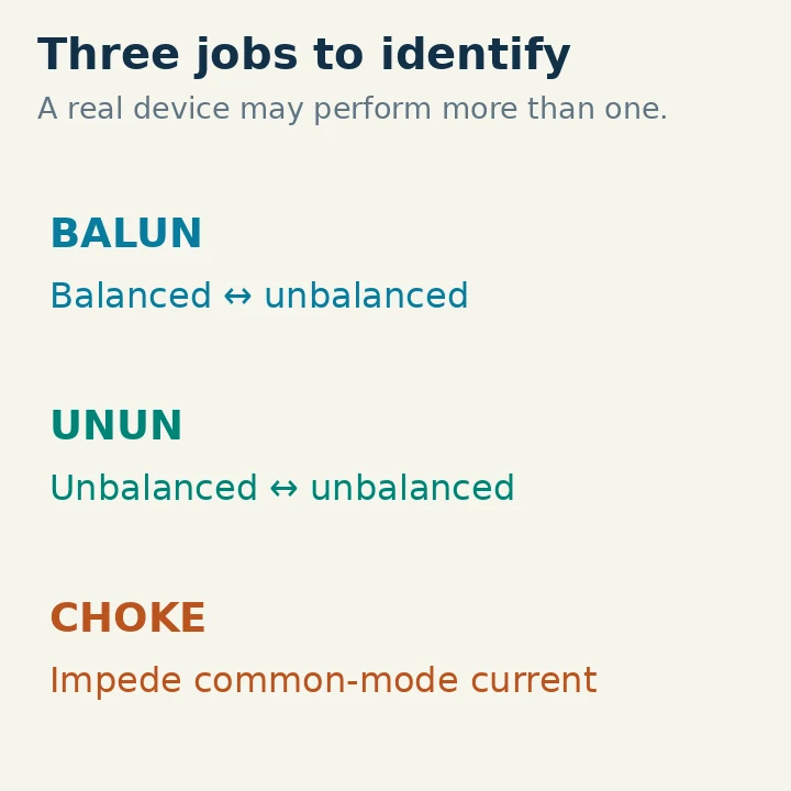
Balun, unun and choke are defined by balanced/unbalanced transition, unbalanced transformation and common-mode impedance respectively; the functions can overlap in one device.
Antennas and Feed Lines · 9 min

Baluns vs Ununs vs Chokes: Principles and Applications

A balun handles a transition between balanced and unbalanced systems. An unun handles an unbalanced-to-unbalanced transformation. A common-mode choke impedes unwanted current flowing in a common-mode path, such as along the outside of a coax shield. These names describe related but different jobs, and one device can perform more than one job.

Read guide →
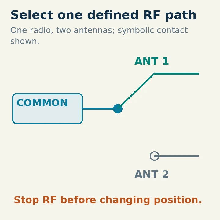
The COMMON port is connected to antenna 1 through a symbolic selector contact while antenna 2 remains unselected; the illustration makes no claim about grounding or termination of unused ports.
Station Setup · 8 min

How to Choose and Use an Antenna Switch

An antenna switch selects an RF path between a common connector and one of several other connectors. In a typical small station, it lets one transceiver use a dipole, a vertical or a dummy load without repeatedly moving coax plugs. Choose it for the actual frequencies, power, duty cycle, connector arrangement and switching job. Then label the paths and change position with transmission stopped.

Read guide →
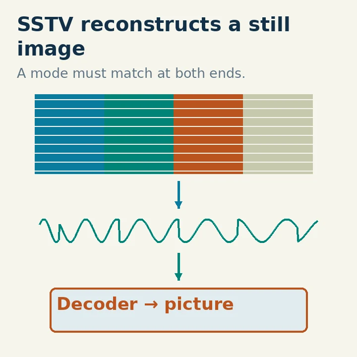
An original abstract color test pattern with scan lines becomes an audio signal and is reconstructed by a matching SSTV decoder; no received image or software screenshot is claimed.
Operating Skills · 7 min

How to Choose SSTV Software

Choose SSTV software by matching your operating system, the kind of SSTV you want to receive or send, and the audio/PTT interfaces your station can provide. Start with a successful receive test using a known mode or recording. A long feature list is less useful than one program that reliably accepts your actual audio source and reconstructs a complete picture.

Read guide →
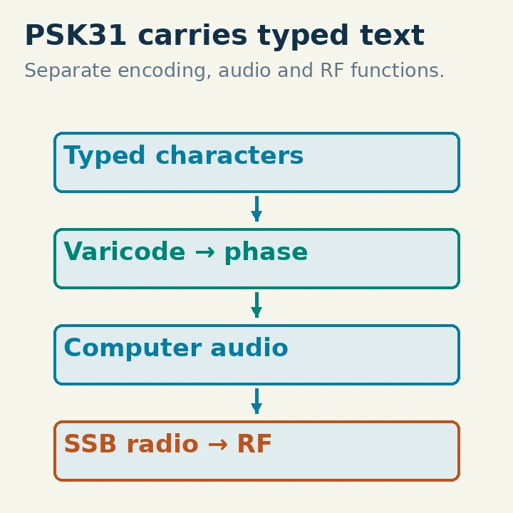
Typed characters are encoded with Varicode and phase modulation, emitted as computer audio and translated to RF by an SSB transceiver.
Operating Skills · 7 min

What Is PSK31 and How Does It Work?

PSK31 is a narrowband digital text mode that sends typed characters over amateur radio by changing a carrier's phase. In the common BPSK31 form, symbols are sent at 31.25 baud, and a variable-length character code turns ordinary text into the transmitted bit stream. A computer sound interface and an SSB transceiver can perform the encoding and decoding.

Read guide →
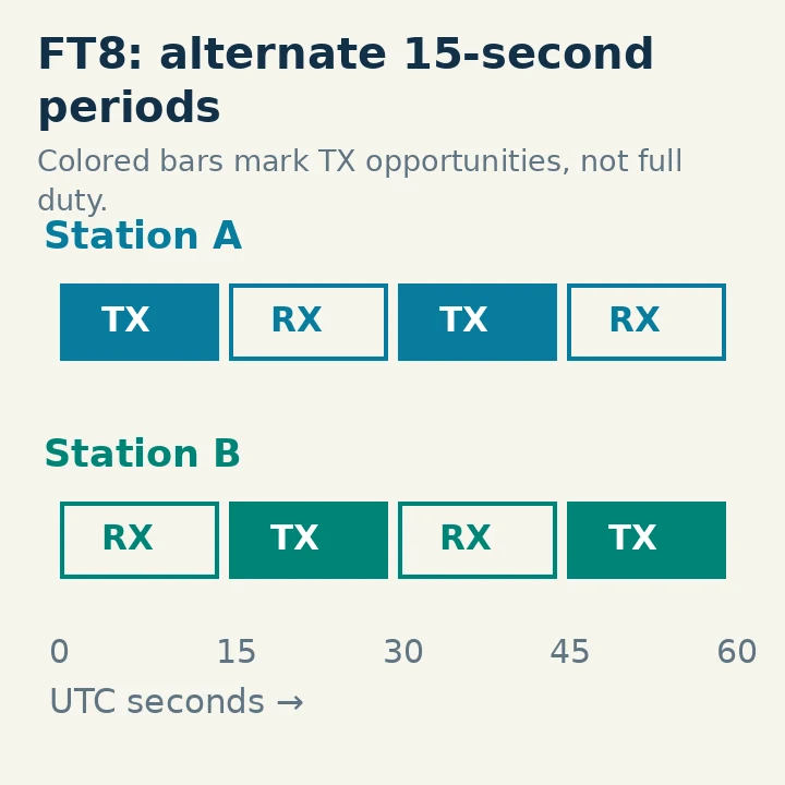
Alternating 15-second FT8 intervals show station A transmitting while B receives, then B transmitting while A receives; the time axis is labeled in UTC seconds.
Operating Skills · 8 min

FT8 Explained: A Beginner’s Guide

FT8 is a narrowband amateur digital mode designed for short, structured contacts under weak-signal conditions. A computer encodes call signs, signal reports and acknowledgments into tones sent through an SSB radio, then decodes replies during alternating receive periods. Ordinary FT8 uses 15-second transmit/receive intervals and occupies about 50 Hz per signal.

Read guide →
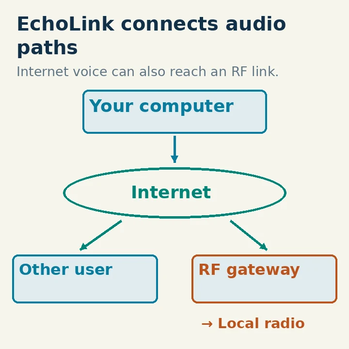
A computer connects through the Internet either to another user or to an RF gateway serving local radio users; an Internet-only session is distinguished from an RF link.
Operating Skills · 7 min

How to Use EchoLink to Connect with Radio Operators Worldwide

To use EchoLink, install an official supported client, register your own amateur call sign, complete license validation, and test your microphone and speaker through the EchoLink test server. Then select an available station, listen before speaking and make a short identified call. You can begin from a computer or supported mobile app without building a radio gateway yourself.

Read guide →
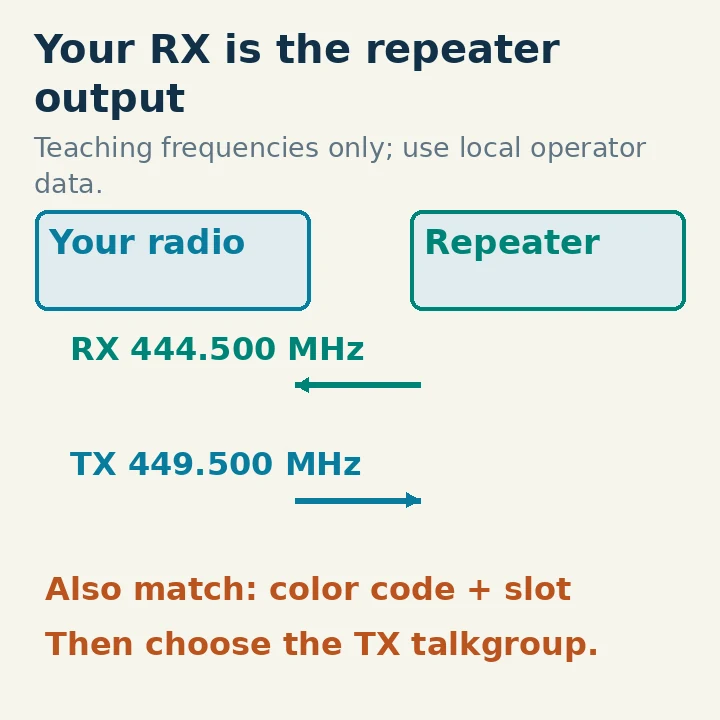
An illustrative repeater sends 444.500 MHz to the radio and receives the radio at 449.500 MHz; color code, time slot and transmit talkgroup are separate requirements.
Operating Skills · 8 min

How Beginners Can Connect a DMR Radio to a Local Repeater

To connect a DMR radio to a local repeater, program the repeater's receive/transmit frequency pair, color code and time slot, then associate the intended talkgroup with a digital contact and channel. Put that channel in a selectable zone, verify reception, and make a short identified call when the slot is clear.

Read guide →